How to Use ESP32 Wroom Wifi: Examples, Pinouts, and Specs
Introduction
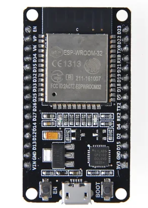
The ESP32 Wroom is a powerful and versatile microcontroller developed by ESP32. It integrates Wi-Fi and Bluetooth capabilities, making it an ideal choice for IoT applications and various embedded systems. With its robust processing power and extensive connectivity options, the ESP32 Wroom is widely used in smart home devices, wearable electronics, industrial automation, and more.
Explore Projects Built with ESP32 Wroom Wifi


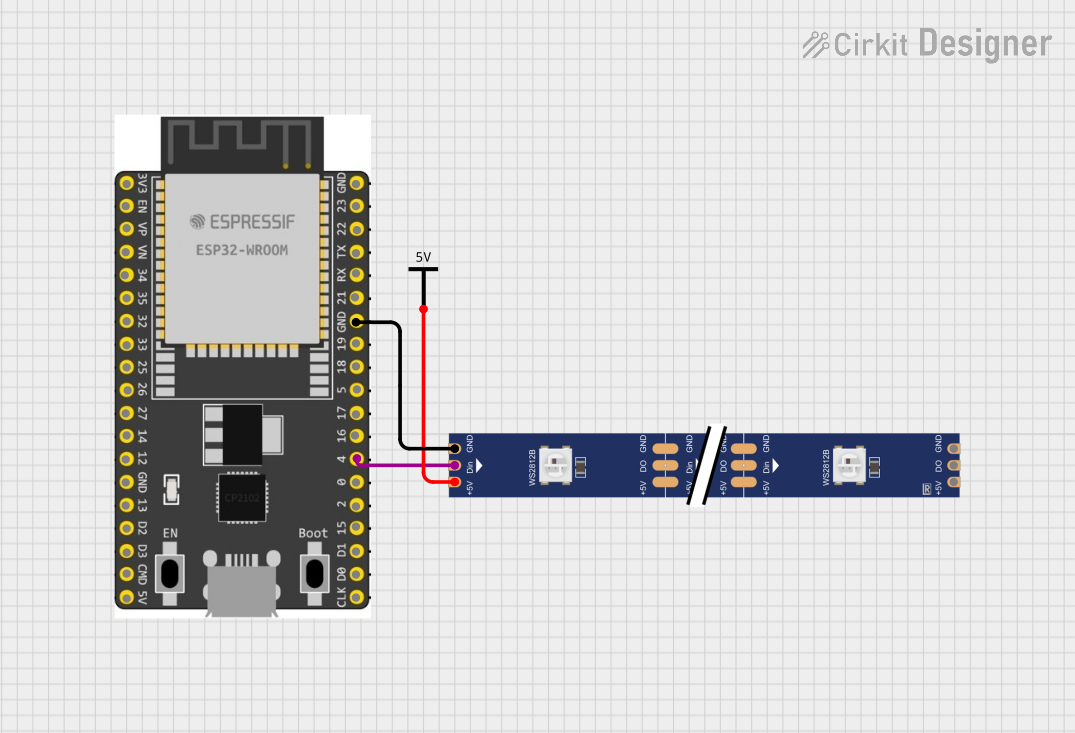
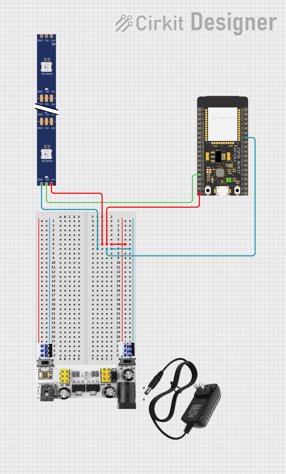
Explore Projects Built with ESP32 Wroom Wifi
Technical Specifications
Key Technical Details
| Parameter | Value |
|---|---|
| Manufacturer | ESP32 |
| Part ID | 32 |
| Operating Voltage | 3.0V - 3.6V |
| Flash Memory | 4MB |
| SRAM | 520KB |
| Wi-Fi Standards | 802.11 b/g/n |
| Bluetooth Version | v4.2 BR/EDR and BLE |
| CPU | Xtensa® Dual-Core 32-bit LX6 |
| Clock Speed | Up to 240 MHz |
| GPIO Pins | 34 |
| ADC Channels | 18 |
| DAC Channels | 2 |
| UART | 3 |
| SPI | 4 |
| I2C | 2 |
| Operating Temperature | -40°C to +85°C |
Pin Configuration and Descriptions
| Pin Number | Pin Name | Description |
|---|---|---|
| 1 | EN | Enable (Active High) |
| 2 | IO0 | GPIO0, Boot Mode Select |
| 3 | IO1 | GPIO1, UART0 TXD |
| 4 | IO2 | GPIO2 |
| 5 | IO3 | GPIO3, UART0 RXD |
| 6 | IO4 | GPIO4 |
| 7 | IO5 | GPIO5 |
| 8 | GND | Ground |
| 9 | 3V3 | 3.3V Power Supply |
| 10 | IO12 | GPIO12, HSPI MISO |
| 11 | IO13 | GPIO13, HSPI MOSI |
| 12 | IO14 | GPIO14, HSPI CLK |
| 13 | IO15 | GPIO15, HSPI CS0 |
| 14 | IO16 | GPIO16, UART2 RXD |
| 15 | IO17 | GPIO17, UART2 TXD |
| 16 | IO18 | GPIO18, VSPI CLK |
| 17 | IO19 | GPIO19, VSPI MISO |
| 18 | IO21 | GPIO21, I2C SDA |
| 19 | IO22 | GPIO22, I2C SCL |
| 20 | IO23 | GPIO23, VSPI MOSI |
| 21 | IO25 | GPIO25, DAC1 |
| 22 | IO26 | GPIO26, DAC2 |
| 23 | IO27 | GPIO27 |
| 24 | IO32 | GPIO32, ADC1_CH4 |
| 25 | IO33 | GPIO33, ADC1_CH5 |
| 26 | IO34 | GPIO34, ADC1_CH6 |
| 27 | IO35 | GPIO35, ADC1_CH7 |
| 28 | IO36 | GPIO36, ADC1_CH0 |
| 29 | IO39 | GPIO39, ADC1_CH3 |
Usage Instructions
How to Use the ESP32 Wroom in a Circuit
- Power Supply: Connect the 3V3 pin to a 3.3V power supply and the GND pin to ground.
- Boot Mode: To upload code, connect GPIO0 to GND and press the EN button.
- GPIO Pins: Use the GPIO pins for interfacing with sensors, actuators, and other peripherals.
- Communication Interfaces: Utilize UART, SPI, and I2C for communication with other devices.
Important Considerations and Best Practices
- Voltage Levels: Ensure that all connected devices operate at 3.3V logic levels to avoid damaging the ESP32.
- Power Supply: Provide a stable power supply to avoid unexpected resets or malfunctions.
- Antenna Placement: For optimal Wi-Fi and Bluetooth performance, place the antenna away from metal objects and other sources of interference.
- Heat Dissipation: Ensure adequate ventilation to prevent overheating, especially in high-performance applications.
Example Code for Arduino UNO
#include <WiFi.h>

// Replace with your network credentials
const char* ssid = "your_SSID";
const char* password = "your_PASSWORD";

void setup() {
  Serial.begin(115200);

  // Connect to Wi-Fi
  WiFi.begin(ssid, password);

  // Wait for connection
  while (WiFi.status() != WL_CONNECTED) {
    delay(1000);
    Serial.println("Connecting to WiFi...");
  }

  Serial.println("Connected to WiFi");
}

void loop() {
  // Put your main code here, to run repeatedly
}
Troubleshooting and FAQs
Common Issues
Wi-Fi Connection Problems:
- Solution: Ensure the correct SSID and password are used. Check for interference from other devices.
Code Upload Failures:
- Solution: Verify that GPIO0 is connected to GND during the upload process. Ensure the correct board and port are selected in the Arduino IDE.
Unexpected Resets:
- Solution: Check the power supply for stability. Ensure that the ESP32 is not overheating.
FAQs
Q1: Can the ESP32 Wroom be powered with 5V?
- A1: No, the ESP32 Wroom operates at 3.3V. Applying 5V can damage the module.
Q2: How do I reset the ESP32 Wroom?
- A2: Press the EN button to reset the module.
Q3: Can I use the ESP32 Wroom with the Arduino IDE?
- A3: Yes, the ESP32 Wroom is compatible with the Arduino IDE. Install the ESP32 board package to get started.
Q4: How do I update the firmware on the ESP32 Wroom?
- A4: Use the ESP32 Flash Download Tool or the Arduino IDE to upload new firmware.
By following this documentation, users can effectively utilize the ESP32 Wroom in their projects, ensuring optimal performance and reliability.