
How to Use SparkFun OpenLog Serial Data Logger: Examples, Pinouts, and Specs

 Design with SparkFun OpenLog Serial Data Logger in Cirkit Designer
Introduction
The SparkFun OpenLog Serial Data Logger (Manufacturer Part ID: DEV-13712) is a compact and versatile data logging module designed to record serial data onto a microSD card. It is an open-source solution that simplifies data collection and analysis from various sensors, microcontrollers, and other serial-enabled devices. With its small form factor and ease of use, the OpenLog is ideal for applications requiring reliable data storage without the need for a computer.
Explore Projects Built with SparkFun OpenLog Serial Data Logger
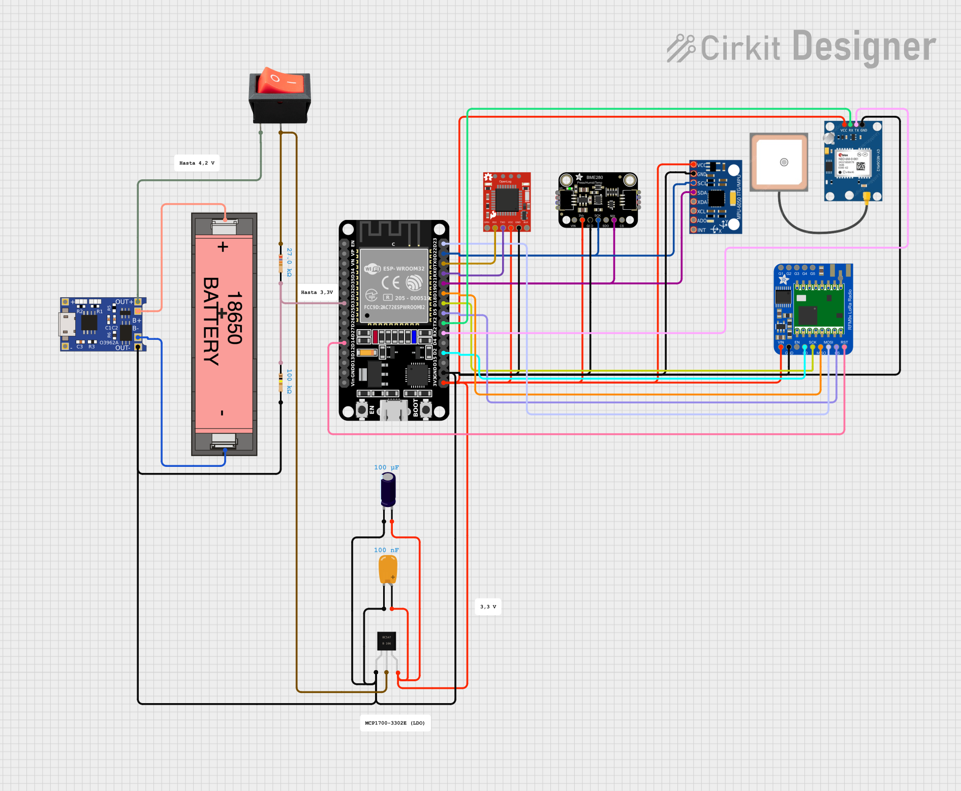 Open Project in Cirkit Designer
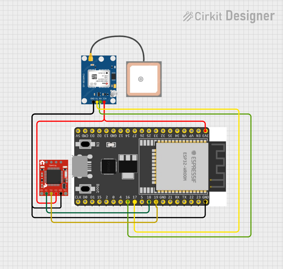 Open Project in Cirkit Designer
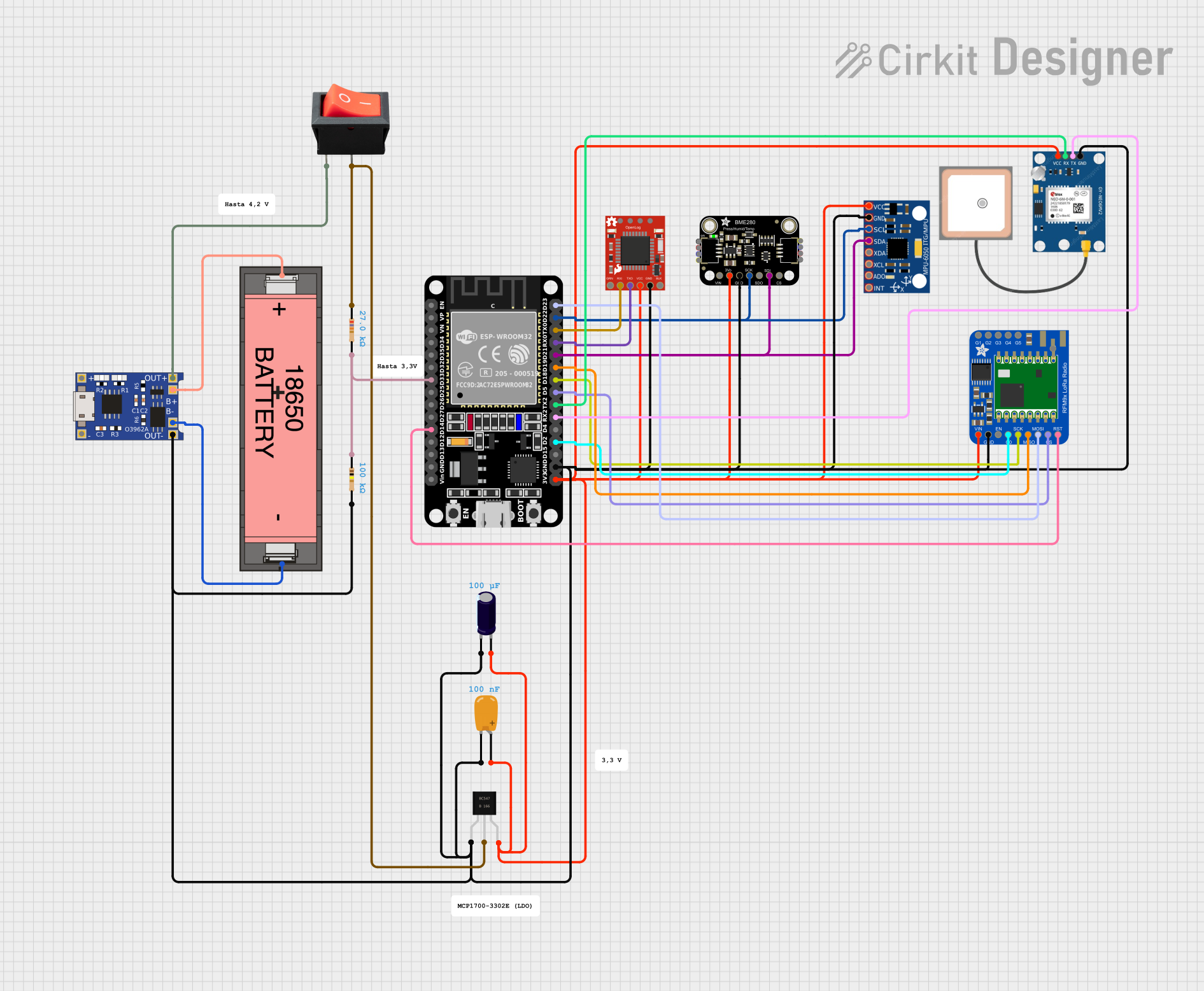 Open Project in Cirkit Designer
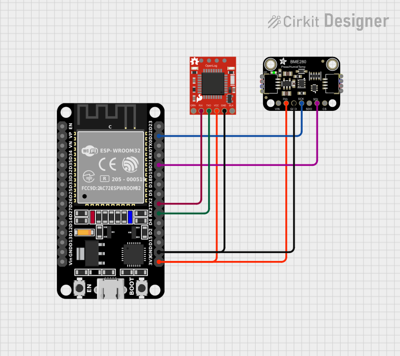 Open Project in Cirkit Designer
Explore Projects Built with SparkFun OpenLog Serial Data Logger
Open Project in Cirkit DesignerOpen Project in Cirkit DesignerOpen Project in Cirkit DesignerOpen Project in Cirkit DesignerCommon Applications and Use Cases
- Logging sensor data from microcontrollers (e.g., Arduino, Raspberry Pi)
- Recording GPS data for navigation and tracking systems
- Storing debugging information during embedded system development
- Collecting data for scientific experiments and research
- Monitoring industrial equipment and processes
Technical Specifications
The following table outlines the key technical details of the SparkFun OpenLog Serial Data Logger:
| Specification | Details |
|---|---|
| Input Voltage Range | 3.3V to 12V |
| Operating Current | ~2mA (idle), ~6mA (logging) |
| Supported Baud Rates | 9600 bps to 115200 bps |
| MicroSD Card Support | FAT16/FAT32 formatted cards, up to 32GB |
| Serial Interface | UART (TX, RX) |
| Dimensions | 15.24mm x 25.4mm (0.6" x 1") |
| Weight | ~2g |
| Firmware | Open-source, customizable |
Pin Configuration and Descriptions
The SparkFun OpenLog has a simple pinout for easy integration into your projects. The table below describes each pin:
| Pin Name | Type | Description |
|---|---|---|
| GND | Power | Ground connection for the module. |
| VCC | Power | Power input (3.3V to 12V). |
| RXI | Input (UART) | Serial data input. Connect to the TX pin of the microcontroller or device. |
| TXO | Output (UART) | Serial data output. Connect to the RX pin of the microcontroller or device. |
| GRN | Debug | Optional pin for resetting the OpenLog or entering bootloader mode. |
Usage Instructions
How to Use the SparkFun OpenLog in a Circuit
- Power the Module: Connect the VCC pin to a 3.3V to 12V power source and the GND pin to ground.
- Connect Serial Lines:
- Connect the RXI pin of the OpenLog to the TX pin of your microcontroller or device.
- Optionally, connect the TXO pin of the OpenLog to the RX pin of your microcontroller for debugging or feedback.
- Insert a microSD Card: Ensure the microSD card is formatted as FAT16 or FAT32 and insert it into the OpenLog.
- Configure Baud Rate: The default baud rate is 9600 bps. If needed, you can change it by editing the
CONFIG.TXTfile on the microSD card. - Start Logging: Once powered and connected, the OpenLog will automatically log any serial data received on the RXI pin.
Important Considerations and Best Practices
- MicroSD Card Preparation: Always format the microSD card as FAT16 or FAT32 before use. Avoid using cards larger than 32GB.
- Baud Rate Matching: Ensure the baud rate of the OpenLog matches the baud rate of the transmitting device.
- Power Supply: Use a stable power source to avoid data corruption or module malfunction.
- Data Backup: Regularly back up data from the microSD card to prevent loss due to card failure.
- Firmware Updates: Check the SparkFun GitHub repository for firmware updates and enhancements.
Example: Using OpenLog with Arduino UNO
Below is an example of how to use the SparkFun OpenLog with an Arduino UNO to log temperature data from a DHT11 sensor:
#include <DHT.h>

// Define DHT sensor pin and type
#define DHTPIN 2
#define DHTTYPE DHT11
DHT dht(DHTPIN, DHTTYPE);

void setup() {
  Serial.begin(9600); // Initialize serial communication at 9600 bps
  dht.begin();        // Initialize the DHT sensor
  delay(1000);        // Allow sensor to stabilize
}

void loop() {
  float temperature = dht.readTemperature(); // Read temperature in Celsius
  float humidity = dht.readHumidity();       // Read humidity percentage

  // Check if the readings are valid
  if (isnan(temperature) || isnan(humidity)) {
    Serial.println("Failed to read from DHT sensor!");
  } else {
    // Log temperature and humidity to OpenLog
    Serial.print("Temperature: ");
    Serial.print(temperature);
    Serial.print(" C, Humidity: ");
    Serial.print(humidity);
    Serial.println(" %");
  }

  delay(2000); // Wait 2 seconds before the next reading
}
Troubleshooting and FAQs
Common Issues and Solutions
No Data Logged on microSD Card
- Ensure the microSD card is properly inserted and formatted as FAT16 or FAT32.
- Verify that the OpenLog is receiving serial data on the RXI pin.
- Check the power supply voltage and current to ensure it meets the module's requirements.
Corrupted Data on microSD Card
- Use a high-quality microSD card to minimize errors.
- Avoid sudden power loss while the OpenLog is writing data.
OpenLog Not Responding
- Check the connections to the VCC and GND pins.
- Reset the module by briefly connecting the GRN pin to ground.
Baud Rate Mismatch
- Ensure the baud rate of the transmitting device matches the OpenLog's baud rate.
- Edit the
CONFIG.TXTfile on the microSD card to set the desired baud rate.
FAQs
Q: Can I use the OpenLog with a 5V microcontroller?
A: Yes, the OpenLog is compatible with 5V logic levels, but ensure the power supply voltage is within the 3.3V to 12V range.
Q: How do I change the baud rate?
A: Edit the CONFIG.TXT file on the microSD card and specify the desired baud rate. Save the file and reinsert the card into the OpenLog.
Q: What happens if the microSD card is full?
A: The OpenLog will stop logging data once the card is full. Regularly monitor and clear the card to ensure sufficient storage space.
Q: Can I log data from multiple devices simultaneously?
A: The OpenLog is designed to log data from a single serial source. For multiple devices, consider using a multiplexer or combining data streams programmatically.