Cirkit Designer Logo
Cirkit Designer
Your all-in-one circuit design IDE
Home / 
Component Documentation

How to Use Keyestudio Reed Switch Sensor Magnetron Module for Arduino: Examples, Pinouts, and Specs

Image of Keyestudio Reed Switch Sensor Magnetron Module for Arduino
Cirkit Designer LogoDesign with Keyestudio Reed Switch Sensor Magnetron Module for Arduino in Cirkit Designer

Introduction

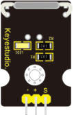
The Keyestudio Reed Switch Sensor Magnetron Module (Part ID: KS0038) is a versatile sensor module designed to detect the presence of a magnetic field. It utilizes a reed switch, which is a mechanical switch that closes its contacts when exposed to a magnetic field. This module is widely used in Arduino projects for applications such as door/window sensors, security systems, and proximity detection.

The module is compact, easy to use, and highly reliable, making it an excellent choice for both beginners and experienced electronics enthusiasts.

Explore Projects Built with Keyestudio Reed Switch Sensor Magnetron Module for Arduino

Use Cirkit Designer to design, explore, and prototype these projects online. Some projects support real-time simulation. Click "Open Project" to start designing instantly!
Arduino Mega 2560-Based Multi-Sensor Alarm System
Image of Expo: A project utilizing Keyestudio Reed Switch Sensor Magnetron Module for Arduino in a practical application
This circuit is designed to interface an Arduino Mega 2560 with a reed switch, flame sensor, PIR sensor, and a buzzer. The sensors are used to detect magnetic fields, flames, and motion, respectively, and can trigger the buzzer or other actions via the Arduino. The circuit is powered through the Arduino, which also serves as the central processing unit to interpret sensor signals and control the buzzer.
Cirkit Designer LogoOpen Project in Cirkit Designer
Arduino Mega 2560 and ESP32 CAM Based Motion Detection and RFID Security System
Image of Arduino Mega Circuit: A project utilizing Keyestudio Reed Switch Sensor Magnetron Module for Arduino in a practical application
This circuit is designed for a multi-sensor motion detection system with image capture and RFID reading capabilities. It uses an Arduino Mega 2560 as the central processing unit, interfacing with microwave radar motion sensors, an ESP32 CAM, and RFID boards. Power management is handled by voltage regulators and DC-DC converters, and an Arduino MKR WiFi 1010 is included for potential wireless communication.
Cirkit Designer LogoOpen Project in Cirkit Designer
Wi-Fi Enabled Smart Lid Status Monitor with NodeMCU and RGB LED
Image of EE 401 1st Demo: A project utilizing Keyestudio Reed Switch Sensor Magnetron Module for Arduino in a practical application
This circuit uses a NodeMCU V3 ESP8266 microcontroller to monitor the state of a reed switch and an IR sensor, and control an RGB LED and a piezo buzzer. The microcontroller reads the reed switch state to determine if a lid is open or closed, and it can also read the IR sensor output. The RGB LED is controlled via digital pins D2, D3, and D4, while the piezo buzzer is activated through pin D7.
Cirkit Designer LogoOpen Project in Cirkit Designer
Arduino UNO Reed Switch Sensor with LED Indicator
Image of Interfacing Reed Switch with Arduino UNO: A project utilizing Keyestudio Reed Switch Sensor Magnetron Module for Arduino in a practical application
This circuit uses an Arduino UNO to monitor the state of a reed switch. When the reed switch is activated by a magnetic field, the Arduino turns on an onboard LED and outputs a message to the serial monitor. The reed switch is connected to the Arduino with an internal pull-up resistor on digital pin D2, and the LED is controlled via pin D13.
Cirkit Designer LogoOpen Project in Cirkit Designer

Explore Projects Built with Keyestudio Reed Switch Sensor Magnetron Module for Arduino

Use Cirkit Designer to design, explore, and prototype these projects online. Some projects support real-time simulation. Click "Open Project" to start designing instantly!
Image of Expo: A project utilizing Keyestudio Reed Switch Sensor Magnetron Module for Arduino in a practical application
Arduino Mega 2560-Based Multi-Sensor Alarm System
This circuit is designed to interface an Arduino Mega 2560 with a reed switch, flame sensor, PIR sensor, and a buzzer. The sensors are used to detect magnetic fields, flames, and motion, respectively, and can trigger the buzzer or other actions via the Arduino. The circuit is powered through the Arduino, which also serves as the central processing unit to interpret sensor signals and control the buzzer.
Cirkit Designer LogoOpen Project in Cirkit Designer
Image of Arduino Mega Circuit: A project utilizing Keyestudio Reed Switch Sensor Magnetron Module for Arduino in a practical application
Arduino Mega 2560 and ESP32 CAM Based Motion Detection and RFID Security System
This circuit is designed for a multi-sensor motion detection system with image capture and RFID reading capabilities. It uses an Arduino Mega 2560 as the central processing unit, interfacing with microwave radar motion sensors, an ESP32 CAM, and RFID boards. Power management is handled by voltage regulators and DC-DC converters, and an Arduino MKR WiFi 1010 is included for potential wireless communication.
Cirkit Designer LogoOpen Project in Cirkit Designer
Image of EE 401 1st Demo: A project utilizing Keyestudio Reed Switch Sensor Magnetron Module for Arduino in a practical application
Wi-Fi Enabled Smart Lid Status Monitor with NodeMCU and RGB LED
This circuit uses a NodeMCU V3 ESP8266 microcontroller to monitor the state of a reed switch and an IR sensor, and control an RGB LED and a piezo buzzer. The microcontroller reads the reed switch state to determine if a lid is open or closed, and it can also read the IR sensor output. The RGB LED is controlled via digital pins D2, D3, and D4, while the piezo buzzer is activated through pin D7.
Cirkit Designer LogoOpen Project in Cirkit Designer
Image of Interfacing Reed Switch with Arduino UNO: A project utilizing Keyestudio Reed Switch Sensor Magnetron Module for Arduino in a practical application
Arduino UNO Reed Switch Sensor with LED Indicator
This circuit uses an Arduino UNO to monitor the state of a reed switch. When the reed switch is activated by a magnetic field, the Arduino turns on an onboard LED and outputs a message to the serial monitor. The reed switch is connected to the Arduino with an internal pull-up resistor on digital pin D2, and the LED is controlled via pin D13.
Cirkit Designer LogoOpen Project in Cirkit Designer

Technical Specifications

Below are the key technical details of the Keyestudio Reed Switch Sensor Magnetron Module:

  • Operating Voltage: 3.3V to 5V
  • Output Type: Digital (High/Low)
  • Switch Type: Normally Open (NO) Reed Switch
  • Dimensions: 30mm x 14mm x 7mm
  • Mounting Hole Diameter: 3mm
  • Indicator LED: Onboard LED to indicate output state
  • Interface: 3-pin header (Signal, VCC, GND)

Pin Configuration and Descriptions

The module has a 3-pin interface, as described in the table below:

Pin Name Description Connection Details
Signal Digital output signal (High/Low) Connect to Arduino digital pin
VCC Power supply (3.3V to 5V) Connect to Arduino 3.3V or 5V pin
GND Ground Connect to Arduino GND pin

Usage Instructions

How to Use the Component in a Circuit
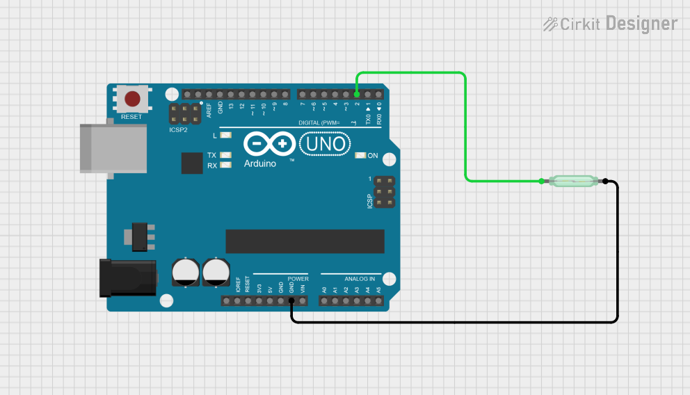
  1. Wiring the Module:

    • Connect the Signal pin of the module to a digital input pin on the Arduino (e.g., D2).
    • Connect the VCC pin to the 5V or 3.3V pin on the Arduino.
    • Connect the GND pin to the GND pin on the Arduino.
  2. Operation:

    • When a magnetic field is brought near the reed switch, the switch closes, and the module outputs a LOW signal (0V).
    • When the magnetic field is removed, the switch opens, and the module outputs a HIGH signal (5V or 3.3V, depending on the supply voltage).
  3. Onboard LED:

    • The onboard LED lights up when the reed switch is activated (i.e., when the output is LOW).

Example Arduino Code

Below is an example Arduino sketch to demonstrate how to use the Keyestudio Reed Switch Sensor Magnetron Module:

// Define the pin connected to the reed switch module
const int reedSwitchPin = 2; // Digital pin 2
const int ledPin = 13;       // Built-in LED pin on Arduino

void setup() {
  pinMode(reedSwitchPin, INPUT); // Set reed switch pin as input
  pinMode(ledPin, OUTPUT);       // Set LED pin as output
  Serial.begin(9600);            // Initialize serial communication
}

void loop() {
  int sensorState = digitalRead(reedSwitchPin); // Read the sensor state

  if (sensorState == LOW) {
    // Magnetic field detected
    digitalWrite(ledPin, HIGH); // Turn on the LED
    Serial.println("Magnetic field detected!");
  } else {
    // No magnetic field detected
    digitalWrite(ledPin, LOW);  // Turn off the LED
    Serial.println("No magnetic field detected.");
  }

  delay(500); // Wait for 500ms before the next reading
}

Important Considerations and Best Practices

  • Debouncing: The reed switch may produce noise or false triggers due to mechanical bouncing. Use software debouncing techniques if necessary.
  • Magnet Placement: Ensure the magnet is placed close enough to activate the reed switch but not so close that it causes constant activation.
  • Voltage Compatibility: Ensure the module's operating voltage matches your microcontroller's logic level (3.3V or 5V).

Troubleshooting and FAQs

Common Issues and Solutions

  1. The module does not detect the magnet:

    • Ensure the magnet is strong enough to activate the reed switch.
    • Verify the wiring connections, especially the Signal, VCC, and GND pins.
    • Check the operating voltage and ensure it matches the module's requirements.
  2. The onboard LED does not light up:

    • Confirm that the module is receiving power (check the VCC and GND connections).
    • Test the module with a multimeter to verify the output signal.
  3. False triggers or unstable readings:

    • Use a pull-up resistor on the Signal pin if the output is unstable.
    • Implement software debouncing in your Arduino code to filter out noise.

FAQs

Q: Can I use this module with a Raspberry Pi?
A: Yes, the module can be used with a Raspberry Pi. Connect the Signal pin to a GPIO pin, and ensure the module is powered with 3.3V to avoid damaging the Pi's GPIO pins.

Q: What type of magnet should I use?
A: Any small neodymium or ferrite magnet should work. Ensure the magnet's strength is sufficient to activate the reed switch.

Q: Is the module polarity-sensitive?
A: No, the reed switch is not polarity-sensitive. However, ensure proper wiring of the VCC and GND pins to avoid damage to the module.

Q: Can I use multiple modules in a single project?
A: Yes, you can use multiple modules by connecting their Signal pins to different digital input pins on your microcontroller.

This concludes the documentation for the Keyestudio Reed Switch Sensor Magnetron Module (KS0038).