How to Use TPS 3 wire: Examples, Pinouts, and Specs

Introduction
The TPS (Throttle Position Sensor) 3 wire is an essential automotive component used to measure the position of the throttle valve in internal combustion engines. It provides real-time feedback to the Engine Control Unit (ECU), enabling precise control of air-fuel mixture and ensuring optimal engine performance, fuel efficiency, and reduced emissions.
This sensor is commonly found in modern vehicles and is critical for applications such as throttle-by-wire systems, cruise control, and engine diagnostics.
Explore Projects Built with TPS 3 wire
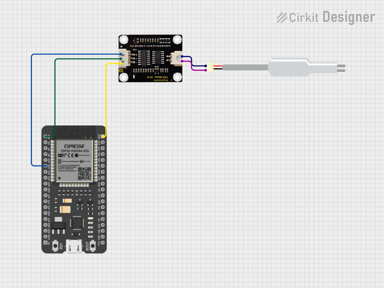


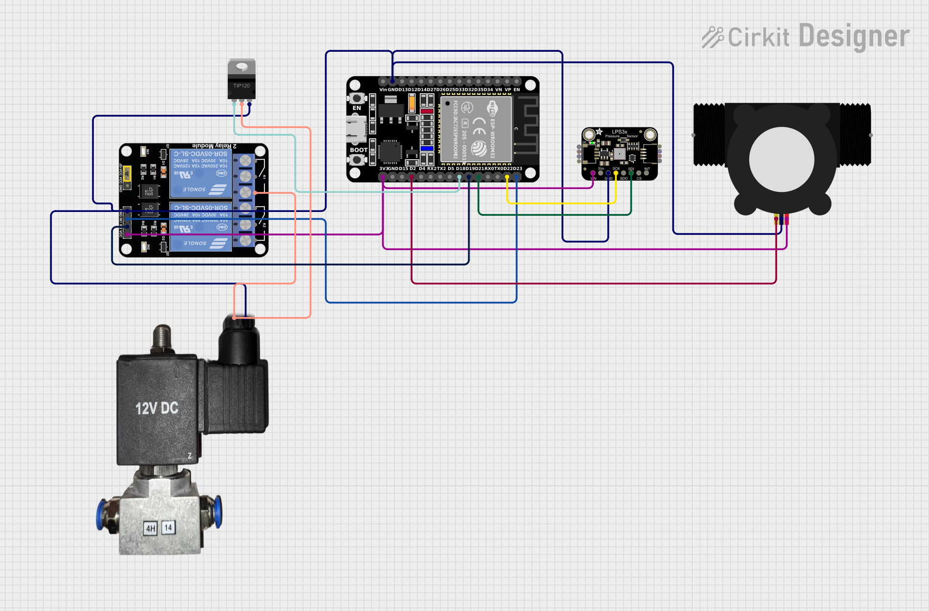
Explore Projects Built with TPS 3 wire
Common Applications and Use Cases
- Automotive throttle control systems
- Engine performance monitoring
- Cruise control systems
- Diagnostics for throttle-related issues
- Integration with Engine Control Units (ECUs)
Technical Specifications
Below are the key technical details and pin configuration for the TPS 3 wire sensor:
Key Technical Details
| Parameter | Value |
|---|---|
| Operating Voltage | 5V DC (typical) |
| Output Signal Type | Analog (0.5V to 4.5V range) |
| Operating Temperature | -40°C to +125°C |
| Sensor Type | Potentiometer-based |
| Accuracy | ±1% of full-scale output |
| Connector Type | 3-pin connector |
Pin Configuration and Descriptions
| Pin Number | Name | Description |
|---|---|---|
| 1 | Ground (GND) | Connects to the vehicle's ground system |
| 2 | Signal (SIG) | Outputs an analog voltage proportional to throttle position |
| 3 | Voltage (VCC) | Connects to a 5V DC power supply |
Usage Instructions
How to Use the TPS 3 Wire in a Circuit
Wiring the Sensor:
- Connect the GND pin to the vehicle's ground or the ground rail of your circuit.
- Connect the VCC pin to a stable 5V DC power supply.
- Connect the SIG pin to the input of the ECU or an analog input pin of a microcontroller for testing purposes.
Reading the Output:
- The sensor outputs an analog voltage that varies between 0.5V (closed throttle) and 4.5V (fully open throttle).
- Use an analog-to-digital converter (ADC) to read the signal if interfacing with a microcontroller.
Calibration:
- Ensure the sensor is properly calibrated to match the throttle's closed and fully open positions. This is typically done during vehicle setup or maintenance.
Important Considerations and Best Practices
- Power Supply: Ensure a stable 5V DC supply to avoid inaccurate readings.
- Signal Noise: Use proper shielding and grounding to minimize electrical noise in the signal line.
- Mechanical Alignment: Verify that the sensor is correctly aligned with the throttle shaft to ensure accurate position measurement.
- Testing: Use a multimeter or an oscilloscope to verify the output voltage range during throttle movement.
Example Code for Arduino UNO
Below is an example of how to read the TPS 3 wire sensor's output using an Arduino UNO:
// Define the analog pin connected to the TPS signal pin
const int tpsPin = A0;

void setup() {
  Serial.begin(9600); // Initialize serial communication at 9600 baud
  pinMode(tpsPin, INPUT); // Set the TPS pin as input
}

void loop() {
  int tpsValue = analogRead(tpsPin); // Read the analog value from the TPS
  float voltage = (tpsValue / 1023.0) * 5.0; // Convert ADC value to voltage

  // Print the voltage to the Serial Monitor
  Serial.print("TPS Voltage: ");
  Serial.print(voltage);
  Serial.println(" V");

  delay(500); // Wait for 500ms before the next reading
}
Note: Ensure the Arduino's ground is connected to the TPS ground for accurate readings.
Troubleshooting and FAQs
Common Issues and Solutions
No Output Signal:
- Cause: Loose or incorrect wiring.
- Solution: Verify all connections, especially the ground and power supply.
Inconsistent or Noisy Signal:
- Cause: Electrical noise or poor grounding.
- Solution: Use shielded cables and ensure proper grounding.
Output Voltage Out of Range:
- Cause: Faulty sensor or incorrect power supply voltage.
- Solution: Check the power supply and replace the sensor if necessary.
ECU Error Codes Related to Throttle Position:
- Cause: Misalignment or calibration issue.
- Solution: Recalibrate the sensor and ensure proper mechanical alignment.
FAQs
Q1: Can the TPS 3 wire sensor be used with microcontrollers other than Arduino?
A1: Yes, the sensor can be used with any microcontroller that has an analog input pin and supports a 5V power supply.
Q2: What happens if the sensor fails?
A2: A failed TPS can cause poor engine performance, erratic idling, or even prevent the engine from starting. It is recommended to replace a faulty sensor immediately.
Q3: How do I test the sensor with a multimeter?
A3: Connect the multimeter's ground probe to the GND pin and the positive probe to the SIG pin. Move the throttle and observe the voltage change between 0.5V and 4.5V.
Q4: Can I use a 3.3V power supply instead of 5V?
A4: No, the TPS 3 wire sensor is designed to operate with a 5V supply. Using a lower voltage may result in inaccurate readings or sensor malfunction.