How to Use PWM Motor speed control: Examples, Pinouts, and Specs
Introduction
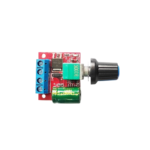
The PWM Motor Speed Control is a versatile electronic component designed to regulate the speed of DC motors by utilizing Pulse Width Modulation (PWM) technology. By varying the width of the pulses in the control signal, this component allows for precise and efficient control of motor speed without significant power loss. It is compatible with a wide range of DC motors operating within a voltage range of 5V to 30V.
Explore Projects Built with PWM Motor speed control


Explore Projects Built with PWM Motor speed control
Common Applications and Use Cases
- Robotics: Controlling the speed of robot wheels or actuators.
- Industrial Automation: Adjusting conveyor belt speeds or machine tools.
- DIY Projects: Custom motorized devices such as fans, pumps, or model vehicles.
- Automotive: Regulating motor speeds in electric vehicles or cooling systems.
Technical Specifications
Below are the key technical details for the PWM Motor Speed Control:
| Parameter | Specification |
|---|---|
| Input Voltage Range | 5V to 30V |
| Output Current | Up to 5A |
| PWM Frequency | 13 kHz |
| Duty Cycle Range | 0% to 100% |
| Control Method | Rotary potentiometer |
| Efficiency | >90% |
| Dimensions | 30mm x 25mm x 15mm |
| Operating Temperature | -20°C to 60°C |
Pin Configuration and Descriptions
The component typically has the following pin connections:
| Pin Name | Description |
|---|---|
| VIN+ | Positive input voltage terminal (5V to 30V). |
| VIN- | Negative input voltage terminal (ground). |
| VOUT+ | Positive output terminal to the motor. |
| VOUT- | Negative output terminal to the motor. |
| Potentiometer | Rotary knob to adjust the PWM duty cycle (speed). |
Usage Instructions
How to Use the Component in a Circuit
- Connect the Power Supply:
- Attach the positive terminal of your DC power supply to the
VIN+pin. - Connect the negative terminal of the power supply to the
VIN-pin.
- Attach the positive terminal of your DC power supply to the
- Connect the Motor:
- Attach the positive terminal of the motor to the
VOUT+pin. - Connect the negative terminal of the motor to the
VOUT-pin.
- Attach the positive terminal of the motor to the
- Adjust the Speed:
- Use the rotary potentiometer to adjust the PWM duty cycle, which controls the motor speed. Turning the knob clockwise increases the speed, while turning it counterclockwise decreases it.
- Power On:
- Turn on the power supply, and the motor will start running at the speed set by the potentiometer.
Important Considerations and Best Practices
- Voltage Compatibility: Ensure the input voltage matches the motor's operating voltage and stays within the 5V to 30V range.
- Current Limitations: Do not exceed the 5A current rating to avoid damaging the component.
- Heat Dissipation: For prolonged use at high currents, consider adding a heat sink to prevent overheating.
- Polarity: Double-check the polarity of all connections to avoid short circuits or damage.
- Noise Filtering: If the motor generates electrical noise, consider adding capacitors across the motor terminals to suppress it.
Example: Using with an Arduino UNO
The PWM Motor Speed Control can also be used with an Arduino UNO to automate speed adjustments. Below is an example code snippet:
// Example: Controlling PWM Motor Speed Control with Arduino UNO
// Connect the PWM Motor Speed Control's potentiometer pin to a PWM pin on Arduino.
// Ensure the motor and Arduino share a common ground.

const int pwmPin = 9; // PWM output pin connected to the motor speed control

void setup() {
  pinMode(pwmPin, OUTPUT); // Set the PWM pin as an output
}

void loop() {
  for (int speed = 0; speed <= 255; speed++) {
    analogWrite(pwmPin, speed); // Gradually increase motor speed
    delay(20); // Wait 20ms between steps
  }
  delay(1000); // Hold at full speed for 1 second

  for (int speed = 255; speed >= 0; speed--) {
    analogWrite(pwmPin, speed); // Gradually decrease motor speed
    delay(20); // Wait 20ms between steps
  }
  delay(1000); // Hold at zero speed for 1 second
}
Troubleshooting and FAQs
Common Issues and Solutions
Motor Does Not Start:
- Cause: Incorrect wiring or insufficient input voltage.
- Solution: Verify all connections and ensure the input voltage is within the 5V to 30V range.
Motor Runs at Full Speed Regardless of Potentiometer Setting:
- Cause: Faulty potentiometer or damaged control circuit.
- Solution: Inspect the potentiometer for damage and replace if necessary.
Overheating:
- Cause: Excessive current draw or poor ventilation.
- Solution: Ensure the motor's current draw does not exceed 5A. Add a heat sink or improve airflow around the component.
PWM Noise Interference:
- Cause: Electrical noise from the motor affecting nearby circuits.
- Solution: Add decoupling capacitors across the motor terminals and use shielded cables.
FAQs
Q: Can this component control multiple motors simultaneously?
A: No, it is designed to control a single motor. For multiple motors, use separate controllers.Q: What happens if I exceed the voltage or current limits?
A: Exceeding the limits can damage the component or the motor. Always operate within the specified range.Q: Can I use this with an AC motor?
A: No, this component is designed for DC motors only.Q: Is it possible to automate speed control without a potentiometer?
A: Yes, you can replace the potentiometer with a PWM signal from a microcontroller like Arduino.
This documentation provides all the necessary details to effectively use the PWM Motor Speed Control in your projects.