Cirkit Designer Logo
Cirkit Designer
Your all-in-one circuit design IDE
Home / 
Component Documentation

How to Use SS14 Schottky Diode: Examples, Pinouts, and Specs

Image of SS14 Schottky Diode
Cirkit Designer LogoDesign with SS14 Schottky Diode in Cirkit Designer

Introduction

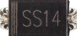
The SS14 is a Schottky diode designed for applications requiring low forward voltage drop and high-speed switching. Its compact design and efficient performance make it ideal for use in power rectification, voltage clamping, and reverse polarity protection circuits. The SS14 is widely used in DC-DC converters, battery chargers, and other power management systems.

Explore Projects Built with SS14 Schottky Diode

Use Cirkit Designer to design, explore, and prototype these projects online. Some projects support real-time simulation. Click "Open Project" to start designing instantly!
Rectifier Diode and LED Circuit with Rocker Switch Control
Image of hypihygi innovations: A project utilizing SS14 Schottky Diode in a practical application
This circuit appears to be a simple power supply circuit with a protection diode and an LED indicator. The diode ensures current flows in only one direction, protecting the circuit from reverse polarity damage. A rocker switch is used to control the power to the LED, which likely serves as an indicator for when the power is on.
Cirkit Designer LogoOpen Project in Cirkit Designer
High-Voltage Electric Fence with Safety Switch
Image of Electric Fence: A project utilizing SS14 Schottky Diode in a practical application
This circuit features a high voltage generator connected to an electric fence, presumably for security or containment purposes. A 9V battery powers the circuit through a rocker switch, which likely serves as the on/off control. The circuit includes diodes for unidirectional current flow and a resistor-LED combination that might indicate the operational status when the fence is powered.
Cirkit Designer LogoOpen Project in Cirkit Designer
Diode and Capacitor-Based Voltage Regulation Circuit
Image of Pavetra#2: A project utilizing SS14 Schottky Diode in a practical application
This circuit is a complex network of diodes and electrolytic capacitors connected to two terminal PCB 2-pin connectors. The diodes are arranged in a series-parallel configuration, while the capacitors are connected in a manner that suggests filtering or energy storage purposes. The overall design appears to be aimed at rectification and smoothing of an input signal.
Cirkit Designer LogoOpen Project in Cirkit Designer
Solar-Powered LED Light with Battery Charging and Light Sensing
Image of ebt: A project utilizing SS14 Schottky Diode in a practical application
This circuit is a solar-powered battery charging and LED lighting system. The solar cell charges a 18650 Li-ion battery through a TP4056 charging module, which also powers a 7805 voltage regulator to provide a stable 5V output. A photocell and MOSFET control the power to a high-power LED, allowing it to turn on or off based on ambient light conditions.
Cirkit Designer LogoOpen Project in Cirkit Designer

Explore Projects Built with SS14 Schottky Diode

Use Cirkit Designer to design, explore, and prototype these projects online. Some projects support real-time simulation. Click "Open Project" to start designing instantly!
Image of hypihygi innovations: A project utilizing SS14 Schottky Diode in a practical application
Rectifier Diode and LED Circuit with Rocker Switch Control
This circuit appears to be a simple power supply circuit with a protection diode and an LED indicator. The diode ensures current flows in only one direction, protecting the circuit from reverse polarity damage. A rocker switch is used to control the power to the LED, which likely serves as an indicator for when the power is on.
Cirkit Designer LogoOpen Project in Cirkit Designer
Image of Electric Fence: A project utilizing SS14 Schottky Diode in a practical application
High-Voltage Electric Fence with Safety Switch
This circuit features a high voltage generator connected to an electric fence, presumably for security or containment purposes. A 9V battery powers the circuit through a rocker switch, which likely serves as the on/off control. The circuit includes diodes for unidirectional current flow and a resistor-LED combination that might indicate the operational status when the fence is powered.
Cirkit Designer LogoOpen Project in Cirkit Designer
Image of Pavetra#2: A project utilizing SS14 Schottky Diode in a practical application
Diode and Capacitor-Based Voltage Regulation Circuit
This circuit is a complex network of diodes and electrolytic capacitors connected to two terminal PCB 2-pin connectors. The diodes are arranged in a series-parallel configuration, while the capacitors are connected in a manner that suggests filtering or energy storage purposes. The overall design appears to be aimed at rectification and smoothing of an input signal.
Cirkit Designer LogoOpen Project in Cirkit Designer
Image of ebt: A project utilizing SS14 Schottky Diode in a practical application
Solar-Powered LED Light with Battery Charging and Light Sensing
This circuit is a solar-powered battery charging and LED lighting system. The solar cell charges a 18650 Li-ion battery through a TP4056 charging module, which also powers a 7805 voltage regulator to provide a stable 5V output. A photocell and MOSFET control the power to a high-power LED, allowing it to turn on or off based on ambient light conditions.
Cirkit Designer LogoOpen Project in Cirkit Designer

Common Applications

  • Power rectification in AC-DC and DC-DC converters
  • Voltage clamping to protect sensitive components
  • Reverse polarity protection in circuits
  • Freewheeling diodes in motor control applications

Technical Specifications

The SS14 Schottky diode is a surface-mount device (SMD) with the following key specifications:

Parameter Value
Maximum Repetitive Peak Reverse Voltage (VRRM) 40V
Maximum Average Forward Rectified Current (IF(AV)) 1A
Peak Forward Surge Current (IFSM) 30A (8.3ms single half sine wave)
Forward Voltage Drop (VF) 0.45V (at 1A)
Reverse Current (IR) 0.5mA (at 40V)
Operating Temperature Range -55°C to +125°C
Package Type SMA (DO-214AC)

Pin Configuration

The SS14 diode has two terminals:

Pin Name Description
1 Anode Positive terminal of the diode
2 Cathode Negative terminal of the diode

The cathode is typically marked with a stripe on the diode's body for easy identification.

Usage Instructions

How to Use the SS14 in a Circuit

  1. Determine the Orientation: Identify the cathode (marked with a stripe) and anode terminals. Connect the anode to the positive side of the circuit and the cathode to the negative side.
  2. Voltage and Current Ratings: Ensure the diode's voltage and current ratings are not exceeded. For example, the reverse voltage should not exceed 40V, and the forward current should not exceed 1A under normal operation.
  3. Soldering: If using the SMD version, solder the SS14 diode onto the PCB pads carefully to avoid overheating the component.
  4. Heat Dissipation: If the diode operates near its maximum current rating, ensure proper heat dissipation by using a PCB with adequate thermal management.

Example: Reverse Polarity Protection with Arduino UNO

The SS14 can be used to protect an Arduino UNO from reverse polarity damage. Below is an example circuit and code:

Circuit Description

  • Connect the SS14 diode in series with the Arduino's power input (VIN pin).
  • The anode of the diode connects to the positive terminal of the power source.
  • The cathode connects to the VIN pin of the Arduino.

Arduino Code Example

// This example demonstrates a simple LED blink program.
// The SS14 diode protects the Arduino from reverse polarity damage.

const int ledPin = 13; // Built-in LED pin on Arduino UNO

void setup() {
  pinMode(ledPin, OUTPUT); // Set the LED pin as an output
}

void loop() {
  digitalWrite(ledPin, HIGH); // Turn the LED on
  delay(1000);                // Wait for 1 second
  digitalWrite(ledPin, LOW);  // Turn the LED off
  delay(1000);                // Wait for 1 second
}

Best Practices

  • Use a heat sink or thermal vias on the PCB if the diode operates at high currents.
  • Avoid exceeding the diode's maximum ratings to prevent damage.
  • For high-frequency applications, ensure the circuit design minimizes parasitic inductance.

Troubleshooting and FAQs

Common Issues

  1. Diode Overheating:

    • Cause: Exceeding the maximum current rating or insufficient heat dissipation.
    • Solution: Reduce the current load or improve thermal management (e.g., use a heat sink).
  2. High Reverse Leakage Current:

    • Cause: Operating the diode at high temperatures or near its reverse voltage limit.
    • Solution: Ensure the diode operates within its specified temperature and voltage range.
  3. Incorrect Orientation:

    • Cause: The diode is installed backward in the circuit.
    • Solution: Verify the cathode stripe and ensure proper orientation during installation.

FAQs

Q1: Can the SS14 handle AC signals?
A1: The SS14 is primarily designed for rectification in DC circuits. However, it can be used in AC circuits for half-wave or full-wave rectification when paired with other diodes.

Q2: What happens if the diode is exposed to a reverse voltage higher than 40V?
A2: Exceeding the reverse voltage rating can cause the diode to break down and fail permanently.

Q3: Is the SS14 suitable for high-frequency applications?
A3: Yes, the SS14's fast switching speed makes it suitable for high-frequency rectification and switching applications.

By following this documentation, users can effectively integrate the SS14 Schottky diode into their electronic designs while avoiding common pitfalls.