How to Use Rhino Motion Controls: Examples, Pinouts, and Specs
Introduction
Rhino Motion Controls (Manufacturer Part ID: 2210007) are advanced systems designed for precise control of motion in various applications. These components are widely used in robotics, automation, and CNC (Computer Numerical Control) machinery to enhance performance, accuracy, and efficiency. They are engineered to provide reliable and smooth motion control, making them ideal for tasks requiring high precision and repeatability.
Explore Projects Built with Rhino Motion Controls

Explore Projects Built with Rhino Motion Controls
Common Applications and Use Cases
- Robotics: Used for controlling robotic arms, mobile robots, and other robotic systems.
- CNC Machinery: Ensures precise movement of tools and workpieces in milling, cutting, and engraving machines.
- Automation Systems: Facilitates smooth and accurate motion in conveyor belts, pick-and-place machines, and other automated systems.
- 3D Printing: Provides precise control of stepper motors for accurate layer deposition.
- Camera Gimbals: Enables smooth and stable motion for professional video recording.
Technical Specifications
Below are the key technical details for the Rhino Motion Controls (Part ID: 2210007):
General Specifications
- Input Voltage Range: 12V to 48V DC
- Maximum Current Output: 5A per phase
- Control Signal Type: Step and Direction
- Microstepping Resolution: Up to 1/256 steps
- Communication Interface: TTL, RS232, or RS485 (depending on model)
- Operating Temperature: -10°C to 50°C
- Dimensions: 120mm x 75mm x 30mm
- Weight: 250g
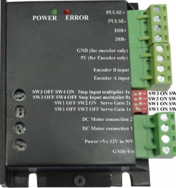
Pin Configuration and Descriptions
The Rhino Motion Controls system typically features a 10-pin connector for interfacing. Below is the pin configuration:
| Pin Number | Pin Name | Description |
|---|---|---|
| 1 | V+ | Positive power supply input (12V to 48V DC). |
| 2 | GND | Ground connection for the power supply. |
| 3 | STEP | Step pulse input for controlling motor steps. |
| 4 | DIR | Direction input to control motor rotation direction. |
| 5 | ENABLE | Enable input to activate or deactivate the driver. |
| 6 | FAULT | Fault output signal to indicate errors (e.g., overcurrent, overheating). |
| 7 | RS485_A | RS485 communication line A (for models with RS485 interface). |
| 8 | RS485_B | RS485 communication line B (for models with RS485 interface). |
| 9 | TTL_RX | TTL receive line for serial communication (for TTL models). |
| 10 | TTL_TX | TTL transmit line for serial communication (for TTL models). |
Usage Instructions
How to Use the Component in a Circuit
- Power Supply: Connect a DC power supply (12V to 48V) to the
V+andGNDpins. Ensure the power supply can provide sufficient current for your motor. - Motor Connection: Connect the stepper motor's wires to the motor output terminals on the Rhino Motion Controls system. Follow the wiring diagram provided in the manufacturer's datasheet.
- Control Signals:
- Connect the
STEPandDIRpins to a microcontroller or motion controller. - Use the
ENABLEpin to activate or deactivate the driver as needed.
- Connect the
- Communication Interface: If using RS485 or TTL communication, connect the appropriate pins (
RS485_A,RS485_B,TTL_RX,TTL_TX) to your controller. - Fault Monitoring: Use the
FAULTpin to monitor error conditions. This pin can be connected to an LED or a microcontroller input for diagnostics.
Important Considerations and Best Practices
- Power Supply: Ensure the power supply voltage and current ratings match the requirements of both the driver and the motor.
- Heat Dissipation: The driver may generate heat during operation. Use a heatsink or active cooling if necessary.
- Signal Integrity: Use shielded cables for control signals to minimize noise interference.
- Microstepping: Configure the microstepping resolution based on your application's precision and speed requirements.
- Fault Handling: Regularly monitor the
FAULTpin to detect and address issues promptly.
Example: Connecting to an Arduino UNO
Below is an example of how to control the Rhino Motion Controls system using an Arduino UNO:
Circuit Connections
- Connect
STEPto Arduino pin 2. - Connect
DIRto Arduino pin 3. - Connect
ENABLEto Arduino pin 4. - Connect
GNDto Arduino GND.
Arduino Code
// Define pin connections
#define STEP_PIN 2  // Pin for step pulses
#define DIR_PIN 3   // Pin for direction control
#define ENABLE_PIN 4 // Pin to enable/disable the driver

void setup() {
  // Set pin modes
  pinMode(STEP_PIN, OUTPUT);
  pinMode(DIR_PIN, OUTPUT);
  pinMode(ENABLE_PIN, OUTPUT);

  // Enable the driver
  digitalWrite(ENABLE_PIN, LOW); // LOW to enable, HIGH to disable
}

void loop() {
  // Set direction
  digitalWrite(DIR_PIN, HIGH); // HIGH for one direction, LOW for the other

  // Generate step pulses
  for (int i = 0; i < 200; i++) { // Move 200 steps
    digitalWrite(STEP_PIN, HIGH);
    delayMicroseconds(500); // Adjust delay for speed
    digitalWrite(STEP_PIN, LOW);
    delayMicroseconds(500);
  }

  delay(1000); // Wait for 1 second before reversing direction

  // Reverse direction
  digitalWrite(DIR_PIN, LOW);

  // Generate step pulses in the opposite direction
  for (int i = 0; i < 200; i++) {
    digitalWrite(STEP_PIN, HIGH);
    delayMicroseconds(500);
    digitalWrite(STEP_PIN, LOW);
    delayMicroseconds(500);
  }

  delay(1000); // Wait for 1 second before repeating
}
Troubleshooting and FAQs
Common Issues and Solutions
Motor Not Moving:
- Cause: Incorrect wiring or insufficient power supply.
- Solution: Double-check all connections and ensure the power supply meets the voltage and current requirements.
Overheating:
- Cause: Prolonged operation at high current or inadequate cooling.
- Solution: Use a heatsink or active cooling to dissipate heat effectively.
Fault Signal Active:
- Cause: Overcurrent, overheating, or other driver faults.
- Solution: Check the motor load, ensure proper cooling, and reset the driver.
Noise or Vibration in Motor:
- Cause: Incorrect microstepping settings or signal interference.
- Solution: Adjust the microstepping resolution and use shielded cables for control signals.
FAQs
Q: Can I use Rhino Motion Controls with a DC motor?
A: No, this driver is specifically designed for stepper motors.Q: What is the maximum cable length for control signals?
A: For TTL signals, keep the cable length under 1 meter. For RS485, you can use cables up to 100 meters.Q: How do I reset the driver after a fault?
A: Power cycle the driver or toggle theENABLEpin to reset it.Q: Can I use this driver with a 24V power supply?
A: Yes, the driver supports a voltage range of 12V to 48V DC.