How to Use ECU S7: Examples, Pinouts, and Specs
Introduction
The ECU S7, manufactured by Syvecs, is a high-performance electronic control unit designed for automotive applications. It serves as the central processing hub for managing various vehicle functions, including engine control, transmission, and other critical systems. By processing data from multiple sensors and executing precise commands, the ECU S7 optimizes vehicle performance, efficiency, and reliability.
Explore Projects Built with ECU S7


Explore Projects Built with ECU S7
Common Applications and Use Cases
- Engine management for high-performance vehicles
- Transmission control in automatic and semi-automatic systems
- Integration with advanced driver-assistance systems (ADAS)
- Data logging and diagnostics for motorsport applications
- Custom tuning for improved fuel efficiency and power output
Technical Specifications
Key Technical Details
| Parameter | Specification |
|---|---|
| Processor | High-speed ARM-based microcontroller |
| Input Voltage Range | 6V to 18V DC |
| Operating Temperature | -40°C to +85°C |
| Communication Protocols | CAN, LIN, RS232 |
| Number of Inputs | 20 analog inputs, 10 digital inputs |
| Number of Outputs | 16 low-side drivers, 8 high-side drivers |
| Memory | 4MB flash memory, 512KB RAM |
| Dimensions | 150mm x 120mm x 40mm |
| Weight | 500g |
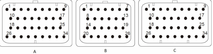
Pin Configuration and Descriptions
The ECU S7 features a 48-pin connector for interfacing with sensors, actuators, and other vehicle systems. Below is the pin configuration:
| Pin Number | Function | Description |
|---|---|---|
| 1 | Power Input (+12V) | Main power supply for the ECU |
| 2 | Ground | Ground connection |
| 3 | CAN High | High line for CAN communication |
| 4 | CAN Low | Low line for CAN communication |
| 5 | Analog Input 1 | Sensor input for analog signals |
| 6 | Analog Input 2 | Sensor input for analog signals |
| 7 | Digital Input 1 | Input for digital signals |
| 8 | Digital Input 2 | Input for digital signals |
| 9 | High-Side Output 1 | Output for driving high-side loads |
| 10 | Low-Side Output 1 | Output for driving low-side loads |
| ... | ... | ... |
| 48 | Reserved | Reserved for future use |
Note: Refer to the official Syvecs ECU S7 datasheet for a complete pinout and wiring diagram.
Usage Instructions
How to Use the ECU S7 in a Circuit
Power Supply:
- Connect the ECU S7 to a stable 12V DC power source.
- Ensure proper grounding to avoid electrical noise or damage.
Sensor Connections:
- Connect analog and digital sensors to the respective input pins.
- Use shielded cables for sensitive signals to minimize interference.
Actuator Connections:
- Connect actuators (e.g., fuel injectors, ignition coils) to the output pins.
- Verify the current and voltage ratings of the actuators to ensure compatibility.
Communication:
- Use the CAN High and CAN Low pins to interface with the vehicle's CAN bus.
- Configure the communication protocol settings (e.g., baud rate) as required.
Programming and Calibration:
- Use the Syvecs software suite to program and calibrate the ECU S7.
- Upload custom maps and configurations for specific vehicle requirements.
Important Considerations and Best Practices
- Heat Management: Install the ECU S7 in a well-ventilated area to prevent overheating.
- Wiring: Use high-quality automotive-grade wiring and connectors to ensure reliability.
- Firmware Updates: Regularly update the ECU firmware to access new features and improvements.
- Diagnostics: Utilize the built-in diagnostics tools to monitor system performance and troubleshoot issues.
Example: Connecting the ECU S7 to an Arduino UNO
The ECU S7 can communicate with an Arduino UNO via the CAN bus. Below is an example code snippet for reading data from the ECU S7 using an Arduino UNO and a CAN module.
#include <SPI.h>
#include <mcp_can.h>

// Define the CAN module's CS pin
#define CAN_CS_PIN 10

// Initialize the CAN object
MCP_CAN CAN(CAN_CS_PIN);

void setup() {
  Serial.begin(9600); // Initialize serial communication for debugging

  // Initialize the CAN bus at 500 kbps
  if (CAN.begin(MCP_ANY, 500000, MCP_8MHZ) == CAN_OK) {
    Serial.println("CAN bus initialized successfully!");
  } else {
    Serial.println("Error initializing CAN bus.");
    while (1); // Halt execution if initialization fails
  }

  CAN.setMode(MCP_NORMAL); // Set CAN module to normal mode
  Serial.println("CAN module set to normal mode.");
}

void loop() {
  unsigned char len = 0;
  unsigned char buf[8];

  // Check if data is available on the CAN bus
  if (CAN.checkReceive() == CAN_MSGAVAIL) {
    CAN.readMsgBuf(&len, buf); // Read the CAN message

    // Print the received data
    Serial.print("Received CAN message: ");
    for (int i = 0; i < len; i++) {
      Serial.print(buf[i], HEX);
      Serial.print(" ");
    }
    Serial.println();
  }

  delay(100); // Add a small delay to avoid flooding the serial monitor
}
Note: Ensure the CAN module is properly connected to the Arduino UNO and the ECU S7. Refer to the CAN module's documentation for wiring details.
Troubleshooting and FAQs
Common Issues and Solutions
ECU Not Powering On:
- Cause: Incorrect power supply or loose connections.
- Solution: Verify the input voltage (6V to 18V DC) and check all power connections.
No Communication via CAN Bus:
- Cause: Incorrect baud rate or wiring issues.
- Solution: Ensure the CAN bus baud rate matches the ECU S7 settings. Check the CAN High and CAN Low connections.
Sensor Readings Are Inaccurate:
- Cause: Electrical noise or incorrect sensor calibration.
- Solution: Use shielded cables for sensor connections and recalibrate the sensors.
Overheating:
- Cause: Poor ventilation or excessive load on outputs.
- Solution: Install the ECU in a well-ventilated area and ensure output loads are within specified limits.
FAQs
Q: Can the ECU S7 be used in electric vehicles?
A: Yes, the ECU S7 can be configured for electric vehicle applications, including motor control and battery management.Q: Does the ECU S7 support over-the-air updates?
A: No, firmware updates must be performed via the Syvecs software suite using a wired connection.Q: What is the maximum current output for the high-side drivers?
A: Each high-side driver can handle up to 5A. Ensure the total load does not exceed the ECU's power capacity.Q: Can I use the ECU S7 for data logging?
A: Yes, the ECU S7 supports data logging via its built-in memory and communication interfaces.
For additional support, refer to the official Syvecs documentation or contact their technical support team.