How to Use MOSFET Drivkort 2-kan 50V 10A: Examples, Pinouts, and Specs
Introduction
The MOSFET Drivkort 2-kan 50V 10A (Manufacturer Part ID: EKM013 - UCC27524) is a dual-channel MOSFET driver circuit designed by Texas Instruments. It is capable of driving MOSFETs with a maximum voltage of 50V and a current rating of 10A. This component is optimized for high-speed switching applications, making it ideal for use in motor control, power supplies, and other high-efficiency systems.
Explore Projects Built with MOSFET Drivkort 2-kan 50V 10A


Explore Projects Built with MOSFET Drivkort 2-kan 50V 10A
Common Applications and Use Cases
- Motor control systems
- DC-DC converters
- High-speed switching circuits
- Synchronous rectification
- Power inverters
- LED drivers
Technical Specifications
The following table outlines the key technical specifications of the MOSFET Drivkort 2-kan 50V 10A:
| Parameter | Value |
|---|---|
| Supply Voltage (VDD) | 4.5V to 18V |
| Maximum Output Voltage | 50V |
| Maximum Output Current | 10A |
| Propagation Delay | 13 ns (typical) |
| Input Threshold Voltage | TTL/CMOS compatible |
| Operating Temperature | -40°C to +140°C |
| Channels | 2 |
| Package Type | SOIC-8 or VSON-8 |
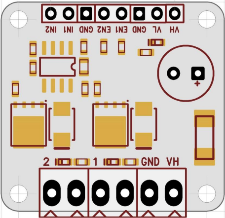
Pin Configuration and Descriptions
The MOSFET Drivkort 2-kan 50V 10A has an 8-pin configuration. The table below describes each pin:
| Pin Number | Pin Name | Description |
|---|---|---|
| 1 | IN1 | Input signal for Channel 1 (TTL/CMOS compatible) |
| 2 | GND | Ground connection |
| 3 | IN2 | Input signal for Channel 2 (TTL/CMOS compatible) |
| 4 | VDD | Supply voltage (4.5V to 18V) |
| 5 | OUT2 | Output signal for Channel 2 (drives the MOSFET gate) |
| 6 | GND | Ground connection (shared with Pin 2) |
| 7 | OUT1 | Output signal for Channel 1 (drives the MOSFET gate) |
| 8 | NC | No connection (leave unconnected or use as a mechanical support point) |
Usage Instructions
How to Use the Component in a Circuit
- Power Supply: Connect the VDD pin to a stable power supply within the range of 4.5V to 18V. Ensure the ground (GND) is properly connected to the circuit's ground.
- Input Signals: Provide TTL/CMOS-compatible input signals to the IN1 and IN2 pins to control the two channels independently.
- Output Connections: Connect the OUT1 and OUT2 pins to the gates of the MOSFETs you wish to drive. Ensure the MOSFETs are rated for the desired voltage and current.
- Bypass Capacitor: Place a decoupling capacitor (e.g., 0.1 µF ceramic) close to the VDD pin to stabilize the power supply and reduce noise.
- Load Considerations: Ensure the load connected to the MOSFETs does not exceed the maximum current and voltage ratings of the driver.
Important Considerations and Best Practices
- Thermal Management: Ensure adequate cooling or heat dissipation for the MOSFETs and driver circuit, especially in high-power applications.
- Signal Integrity: Use short and low-inductance traces for the input and output connections to minimize noise and signal degradation.
- Dead Time: If used in a half-bridge or full-bridge configuration, ensure proper dead time between switching to prevent shoot-through currents.
- Protection: Add appropriate protection components (e.g., diodes, resistors) to safeguard the circuit from voltage spikes or transients.
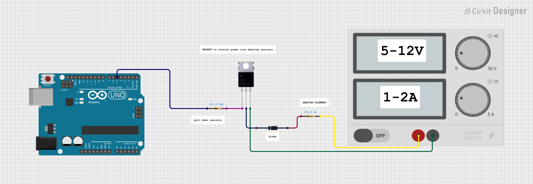
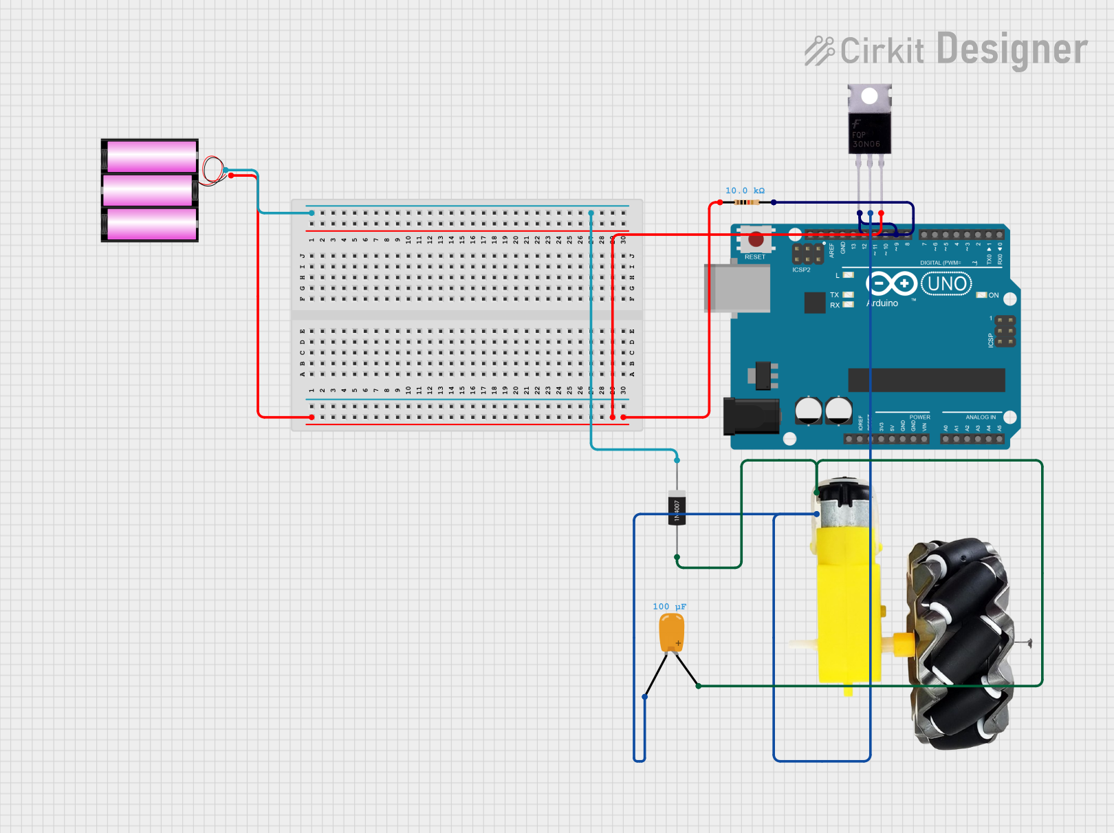
Example: Using with Arduino UNO
The following example demonstrates how to control the MOSFET Drivkort 2-kan 50V 10A using an Arduino UNO to drive two MOSFETs.
// Define the input pins for the MOSFET driver
const int channel1 = 9; // PWM pin for Channel 1
const int channel2 = 10; // PWM pin for Channel 2

void setup() {
  // Set the pins as outputs
  pinMode(channel1, OUTPUT);
  pinMode(channel2, OUTPUT);
}

void loop() {
  // Example: Generate a PWM signal on Channel 1
  analogWrite(channel1, 128); // 50% duty cycle (value range: 0-255)

  // Example: Generate a PWM signal on Channel 2
  analogWrite(channel2, 192); // 75% duty cycle (value range: 0-255)

  delay(1000); // Wait for 1 second

  // Turn off both channels
  analogWrite(channel1, 0);
  analogWrite(channel2, 0);

  delay(1000); // Wait for 1 second
}
Troubleshooting and FAQs
Common Issues and Solutions
No Output Signal:
- Cause: Incorrect power supply or loose connections.
- Solution: Verify the VDD and GND connections. Ensure the supply voltage is within the specified range (4.5V to 18V).
MOSFET Overheating:
- Cause: Insufficient dead time or excessive load current.
- Solution: Add dead time in the control signals and ensure the load does not exceed the MOSFET's ratings.
High Noise or Instability:
- Cause: Poor PCB layout or lack of decoupling capacitors.
- Solution: Use short traces for high-speed signals and place a 0.1 µF capacitor close to the VDD pin.
Driver Not Responding to Input:
- Cause: Input signal not TTL/CMOS compatible.
- Solution: Verify the input signal levels and ensure they meet the driver's requirements.
FAQs
Q1: Can this driver be used for IGBTs instead of MOSFETs?
A1: Yes, the driver can be used for IGBTs as long as the voltage and current requirements are within the specified limits.
Q2: What is the maximum switching frequency supported?
A2: The driver supports high-speed switching with a typical propagation delay of 13 ns, making it suitable for frequencies up to several MHz.
Q3: Can I use this driver with a 3.3V microcontroller?
A3: Yes, the input pins are TTL/CMOS compatible and can accept signals as low as 3.3V.
Q4: Is it necessary to use both channels?
A4: No, you can use a single channel if your application only requires one MOSFET to be driven. Leave the unused channel's input unconnected or tied to GND.