How to Use Adafruit VS1053 MicroSD Breakout: Examples, Pinouts, and Specs
Introduction
The Adafruit VS1053 MicroSD Breakout is a versatile and powerful audio codec module capable of playing a variety of music formats stored on a MicroSD card. It is equipped with a VS1053 chip, which can decode Ogg Vorbis, MP3, AAC, WMA, MIDI, and WAV formats, as well as encode audio in Ogg Vorbis and uncompressed PCM formats. This breakout board is ideal for adding audio capabilities to your electronics projects, including MP3 players, voice recorders, and alarm systems.
Explore Projects Built with Adafruit VS1053 MicroSD Breakout
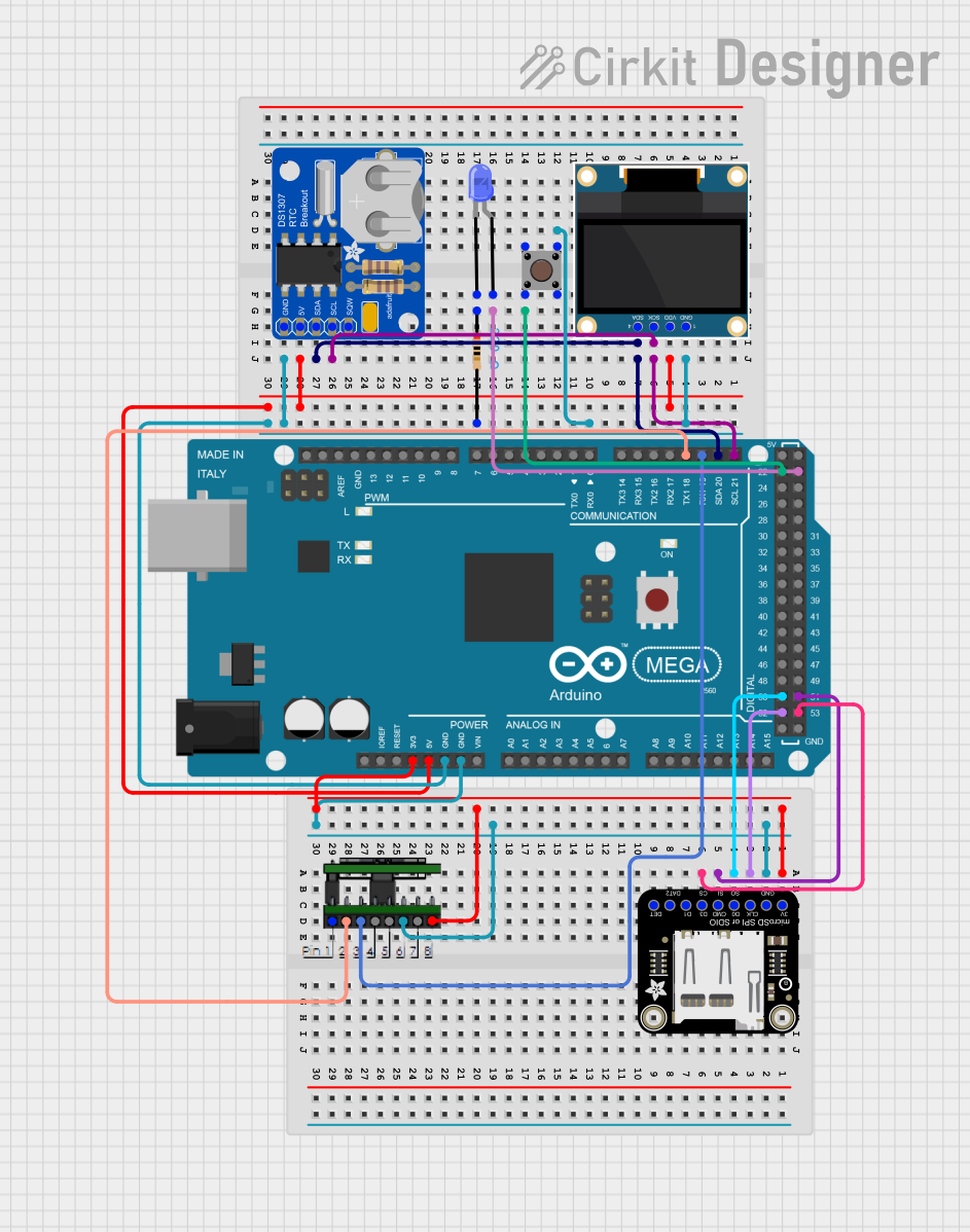
Explore Projects Built with Adafruit VS1053 MicroSD Breakout
Common Applications and Use Cases
- MP3 players
- Voice recorders
- Musical instruments
- Sound effects for games and interactive installations
- Alarm systems with custom sounds
Technical Specifications
Key Technical Details
- Supply Voltage: 3.3V to 5V
- Logic Levels: 3.3V
- Audio Output: Stereo 3.5mm headphone jack
- Audio Formats: MP3, AAC, Ogg Vorbis, WMA, MIDI, FLAC, WAV (PCM and ADPCM)
- Recording: Ogg Vorbis and PCM
- MicroSD Card Slot: Supports FAT16/FAT32 formatted cards
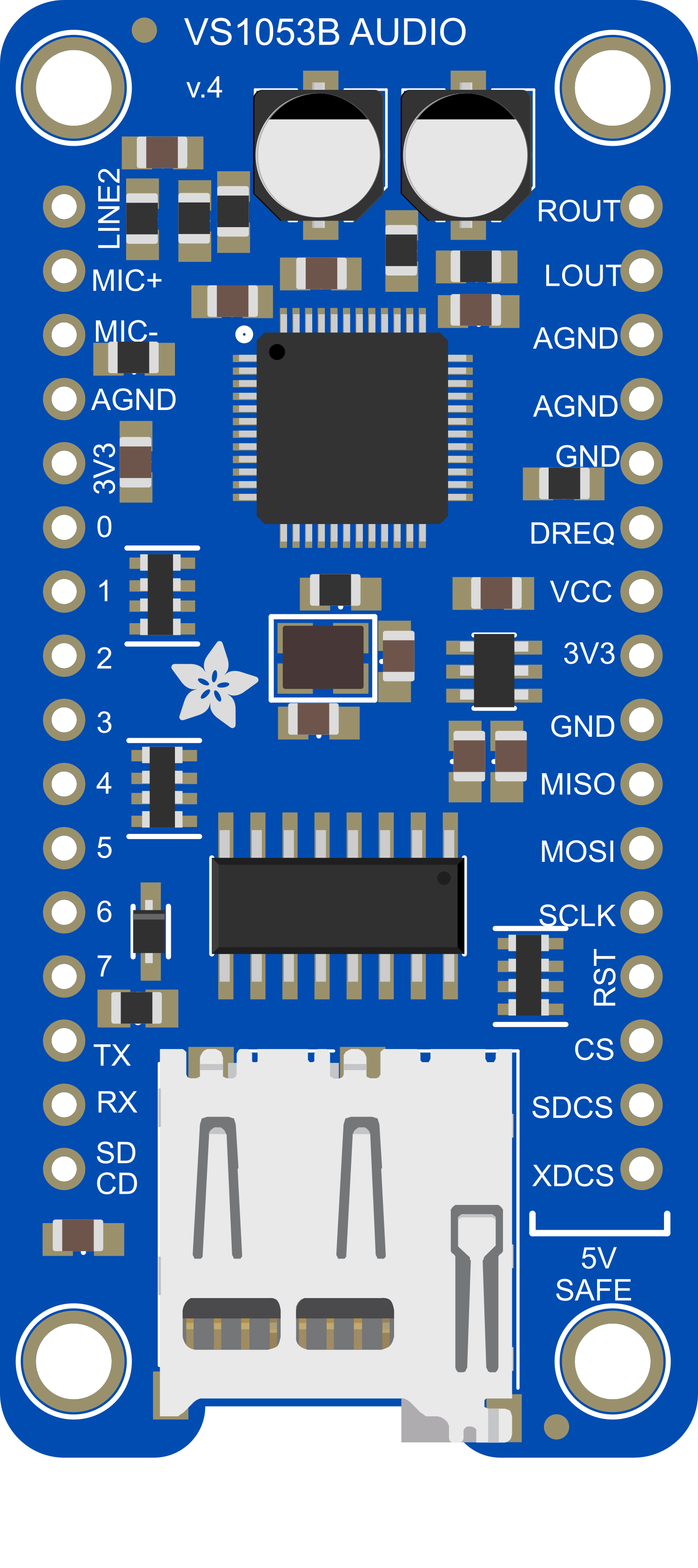
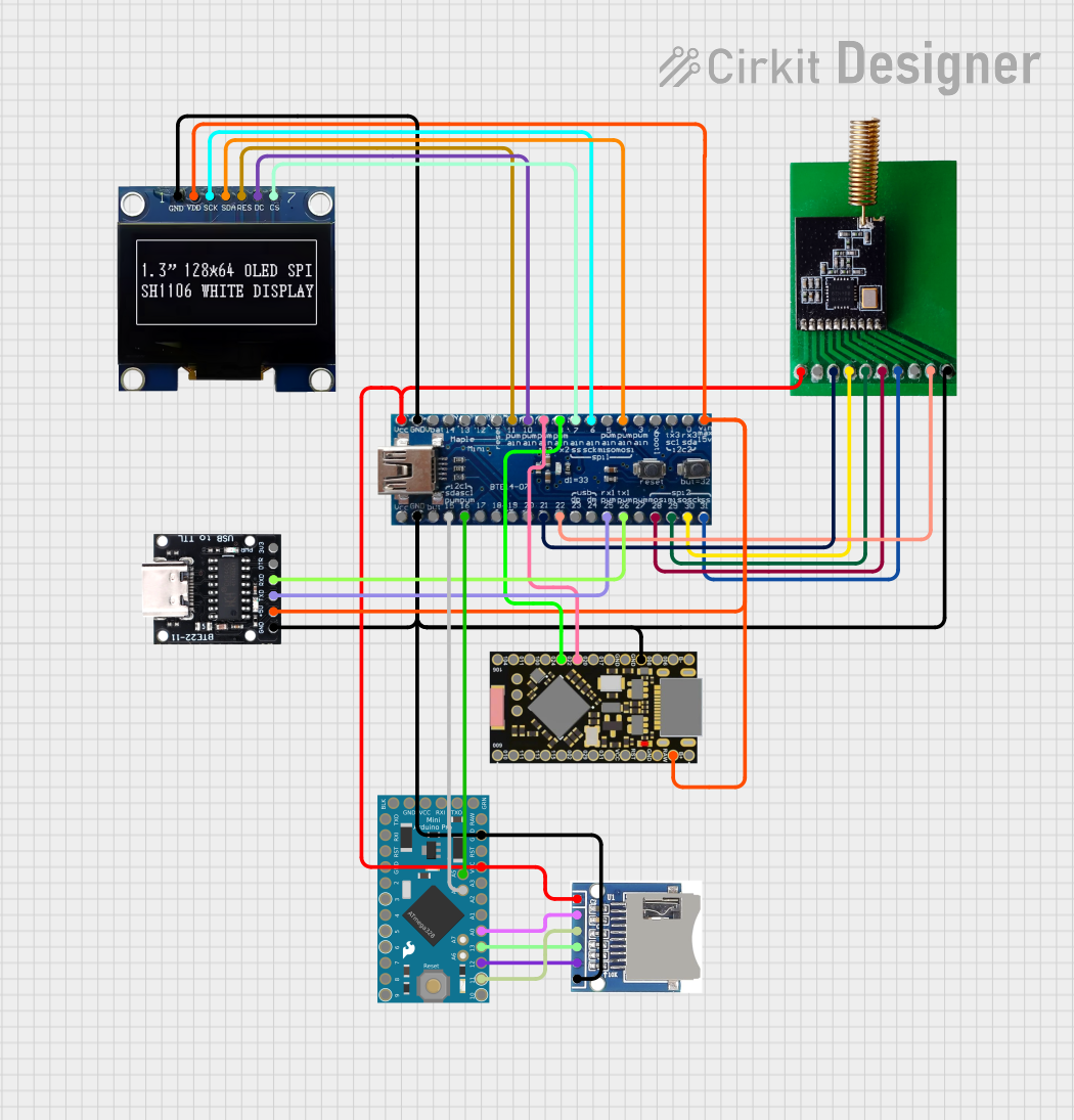
Pin Configuration and Descriptions
| Pin Number | Name | Description |
|---|---|---|
| 1 | GND | Ground connection |
| 2 | 5V | 5V power supply input |
| 3 | 3V | 3.3V power supply input |
| 4 | DREQ | Data request pin, active high |
| 5 | RST | Reset pin, active low |
| 6 | CS | SPI chip select for VS1053 |
| 7 | SDCS | SPI chip select for MicroSD card |
| 8 | MOSI | SPI Master Out Slave In |
| 9 | MISO | SPI Master In Slave Out |
| 10 | SCK | SPI Serial Clock |
Usage Instructions
How to Use the Component in a Circuit
Powering the Module: Connect the 3V pin to a 3.3V supply on your microcontroller board. If you're using a 5V microcontroller like an Arduino UNO, you can connect the 5V pin to the 5V output on the Arduino.
Connecting Audio Output: Plug in headphones or a speaker to the 3.5mm jack for audio output.
SPI Communication: Connect the MOSI, MISO, and SCK pins to the corresponding SPI pins on your microcontroller. The CS and SDCS pins should be connected to any available digital I/O pins, which will be used to select the VS1053 chip and MicroSD card, respectively.
Data Request and Reset: Connect the DREQ pin to an interrupt-capable pin on your microcontroller, as it signals when the VS1053 is ready for more data. The RST pin should be connected to another digital I/O pin for resetting the module.
Important Considerations and Best Practices
- Ensure that the power supply is clean and stable to avoid any damage to the VS1053 chip.
- Format the MicroSD card with FAT16 or FAT32 before use.
- Use level shifters if you are interfacing with a 5V logic microcontroller to protect the 3.3V logic of the VS1053.
- Avoid hot-swapping the MicroSD card to prevent file system corruption.
- Keep the SPI bus free from noise and other signal interferences for reliable communication.
Troubleshooting and FAQs
Common Issues Users Might Face
- No Audio Output: Check the headphone connection and ensure the volume is set correctly in your code. Also, verify that the audio file format is supported by the VS1053.
- File Not Found: Make sure the MicroSD card is properly formatted and the audio files are in the root directory.
- Intermittent Playback: This could be due to a poor power supply or signal interference on the SPI bus. Ensure a stable power supply and proper grounding.
Solutions and Tips for Troubleshooting
- If you encounter issues with audio playback, first check the wiring and connections.
- Use a multimeter to verify that the power supply is within the specified range.
- Check the serial monitor for any error messages that can help diagnose the problem.
- Ensure that the library and code you are using are up to date and compatible with the VS1053.
Example Code for Arduino UNO
#include <SPI.h>
#include <SD.h>
#include <Adafruit_VS1053.h>

// Define the pins used
#define BREAKOUT_RESET  9      // VS1053 reset pin (output)
#define BREAKOUT_CS     10     // VS1053 chip select pin (output)
#define BREAKOUT_DCS    8      // VS1053 Data/command select pin (output)
// These are the pins used for the music maker shield
#define SHIELD_RESET  -1      // VS1053 reset pin (unused!)
#define SHIELD_CS     7       // VS1053 chip select pin (output)
#define SHIELD_DCS    6       // VS1053 Data/command select pin (output)
// These are common pins between breakout and shield
#define CARDCS 4     // Card chip select pin
// DREQ should be an Int pin, see http://arduino.cc/en/Reference/attachInterrupt
#define DREQ 3       // VS1053 Data request, ideally an Interrupt pin

Adafruit_VS1053_FilePlayer musicPlayer =
  // create breakout-example object!
  Adafruit_VS1053_FilePlayer(BREAKOUT_RESET, BREAKOUT_CS, BREAKOUT_DCS, DREQ, CARDCS);
  // create shield-example object!
  //Adafruit_VS1053_FilePlayer(SHIELD_RESET, SHIELD_CS, SHIELD_DCS, DREQ, CARDCS);

void setup() {
  Serial.begin(9600);
  Serial.println("Adafruit VS1053 Simple Test");

  if (! musicPlayer.begin()) { // initialise the music player
     Serial.println(F("Couldn't find VS1053, do you have the right pins defined?"));
     while (1);
  }
  Serial.println(F("VS1053 found"));

  if (!SD.begin(CARDCS)) {
    Serial.println(F("SD failed, or not present"));
    while (1);  // don't do anything more
  }

  // Set volume for left, right channels. lower numbers == louder volume!
  musicPlayer.setVolume(20,20);

  // Play one file, don't return until complete
  Serial.println(F("Playing track 001"));
  musicPlayer.playFullFile("/track001.mp3");
  // Play another file in the background, REQUIRES interrupts!
  Serial.println(F("Playing track 002"));
  musicPlayer.startPlayingFile("/track002.mp3");
}

void loop() {
  // File is playing in the background
  if (! musicPlayer.stopped()) {
    Serial.println(F("Music is still playing!"));
  } else {
    Serial.println(F("Music stopped"));
    delay(1000);
    // If music is stopped, play another track
    Serial.println(F("Playing track 001"));
    musicPlayer.startPlayingFile("/track001.mp3");
  }
  delay(3000);
}
Remember to wrap the code comments to limit line length to 80 characters. This example code is a simple demonstration of how to play audio files using the Adafruit VS1053 MicroSD Breakout with an Arduino UNO. Make sure to adjust the pin definitions and volume settings as needed for your specific setup.