How to Use SIM800L V2 EVB GSM MODULE: Examples, Pinouts, and Specs
Introduction
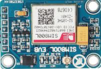
The SIM800L V2 EVB GSM Module (Manufacturer: ROHS, Part ID: MOD31) is a compact and versatile GSM/GPRS module designed for communication over cellular networks. It supports SMS, voice calls, and data transmission, making it an ideal choice for Internet of Things (IoT) applications. The module operates on a wide voltage range and features an onboard antenna connector for enhanced signal reception.
Explore Projects Built with SIM800L V2 EVB GSM MODULE
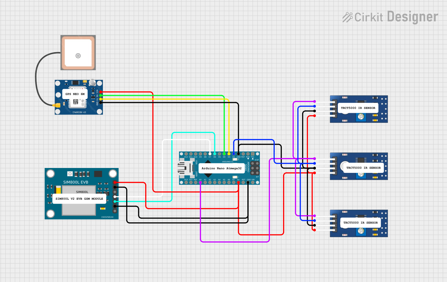
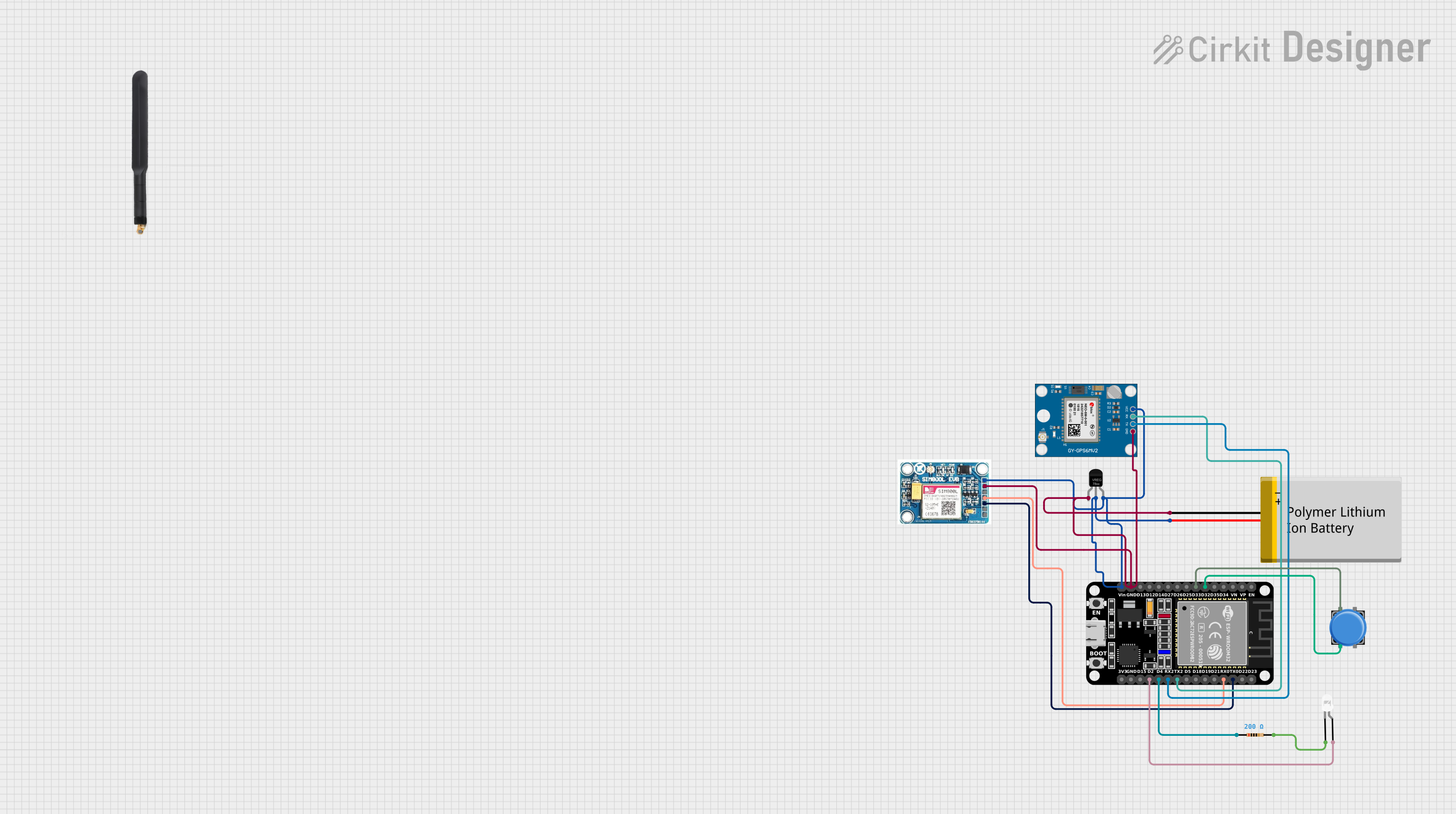

Explore Projects Built with SIM800L V2 EVB GSM MODULE
Common Applications and Use Cases
- IoT devices requiring cellular connectivity
- Remote monitoring and control systems
- GPS tracking and fleet management
- Home automation and smart appliances
- SMS-based alert systems
- Voice communication in embedded systems
Technical Specifications
Key Technical Details
| Parameter | Specification |
|---|---|
| Operating Voltage | 3.7V to 4.2V |
| Recommended Voltage | 4.0V |
| Power Consumption | Idle: ~1mA, Active: ~200mA, Peak: ~2A |
| Frequency Bands | GSM 850/900/1800/1900 MHz |
| Communication Protocols | GSM/GPRS (Class 10) |
| Data Transmission Speed | Up to 85.6 kbps (GPRS) |
| SIM Card Support | Micro SIM |
| Antenna Connector | IPX/U.FL |
| Dimensions | 25mm x 23mm x 3mm |
| Operating Temperature | -40°C to +85°C |
Pin Configuration and Descriptions
The SIM800L V2 EVB module has 8 pins. Below is the pinout and description:
| Pin Number | Pin Name | Description |
|---|---|---|
| 1 | VCC | Power input (3.7V to 4.2V). Ensure stable power supply with sufficient current. |
| 2 | GND | Ground connection. |
| 3 | RXD | UART Receive pin. Connect to the TX pin of the microcontroller. |
| 4 | TXD | UART Transmit pin. Connect to the RX pin of the microcontroller. |
| 5 | RST | Reset pin. Active LOW. Pull LOW to reset the module. |
| 6 | NET | Network status indicator (blinks to indicate GSM status). |
| 7 | DTR | Data Terminal Ready. Used for sleep mode control. |
| 8 | MIC+ | Microphone positive input for voice communication. |
Usage Instructions
How to Use the SIM800L V2 EVB in a Circuit
Power Supply:
- Use a stable power source capable of providing 3.7V to 4.2V with at least 2A peak current.
- A LiPo battery or a DC-DC buck converter is recommended for reliable operation.
- Connect the power source to the
VCCandGNDpins.
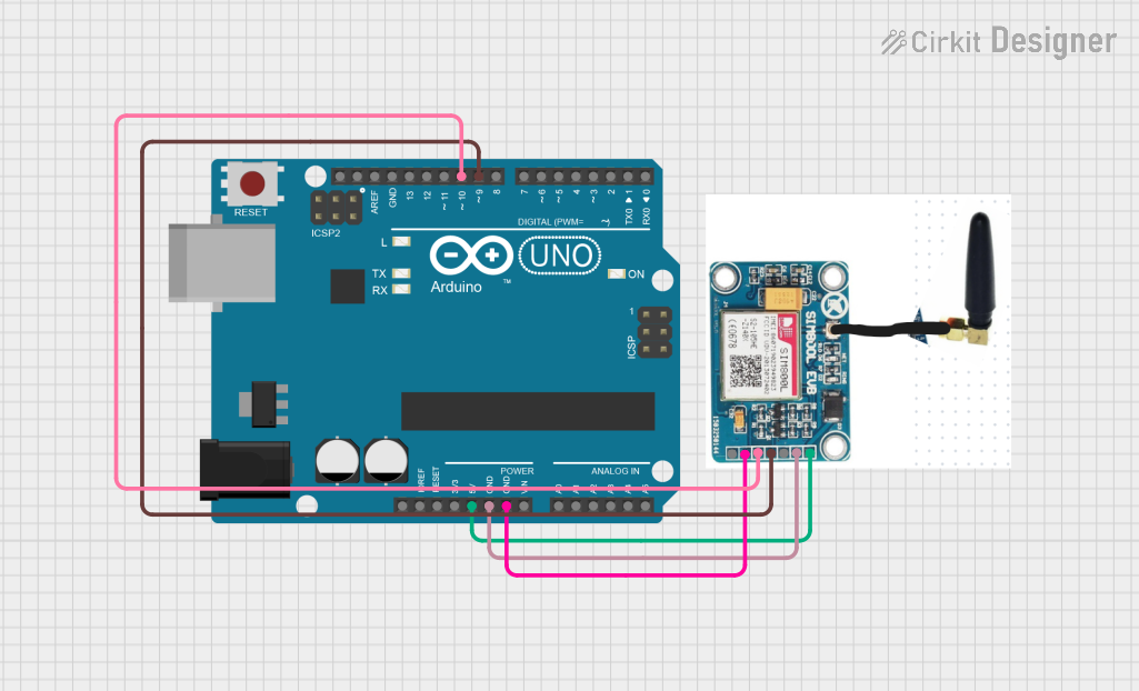
Microcontroller Connection:
- Connect the
TXDpin of the SIM800L to theRXpin of the microcontroller. - Connect the
RXDpin of the SIM800L to theTXpin of the microcontroller. - Use a logic level shifter if your microcontroller operates at 5V logic levels, as the SIM800L uses 3.3V logic.
- Connect the
Antenna:
- Attach an IPX/U.FL antenna to the onboard connector for better signal reception.
SIM Card:
- Insert a micro SIM card into the SIM card slot. Ensure the card is activated and has sufficient balance for SMS, calls, or data.
Reset and Sleep Mode:
- Use the
RSTpin to reset the module if needed. - The
DTRpin can be used to enable sleep mode for power saving.
- Use the
Network Status:
- Monitor the
NETpin to check the GSM network status. The blinking pattern indicates the connection state.
- Monitor the
Arduino UNO Example Code
Below is an example of how to send an SMS using the SIM800L module with an Arduino UNO:
#include <SoftwareSerial.h>

// Define RX and TX pins for SoftwareSerial
SoftwareSerial SIM800L(10, 11); // RX = Pin 10, TX = Pin 11

void setup() {
  // Initialize serial communication
  Serial.begin(9600); // For debugging
  SIM800L.begin(9600); // For SIM800L communication

  // Wait for the module to initialize
  delay(1000);
  Serial.println("Initializing SIM800L...");

  // Send AT command to check communication
  SIM800L.println("AT");
  delay(1000);
  while (SIM800L.available()) {
    Serial.write(SIM800L.read());
  }

  // Set SMS text mode
  SIM800L.println("AT+CMGF=1"); // Set SMS to text mode
  delay(1000);

  // Send SMS
  SIM800L.println("AT+CMGS=\"+1234567890\""); // Replace with recipient's phone number
  delay(1000);
  SIM800L.println("Hello from SIM800L!"); // SMS content
  delay(1000);
  SIM800L.write(26); // Send Ctrl+Z to send the SMS
  delay(5000);

  Serial.println("SMS sent!");
}

void loop() {
  // No actions in the loop
}
Important Considerations and Best Practices
- Ensure the power supply can handle the module's peak current of 2A to avoid unexpected resets.
- Use a decoupling capacitor (e.g., 1000µF) near the
VCCpin to stabilize the power supply. - Place the antenna away from other components to minimize interference.
- Avoid using the module in areas with poor GSM signal strength to prevent excessive power consumption.
Troubleshooting and FAQs
Common Issues and Solutions
Module Keeps Restarting:
- Cause: Insufficient power supply.
- Solution: Use a power source capable of providing at least 2A peak current. Add a decoupling capacitor near the
VCCpin.
No Network Connection:
- Cause: Poor signal strength or incorrect SIM card.
- Solution: Check the antenna connection and ensure the SIM card is activated and inserted correctly.
No Response to AT Commands:
- Cause: Incorrect UART connection or baud rate.
- Solution: Verify the
RXDandTXDconnections. Ensure the baud rate matches the module's default (9600 bps).
SMS Not Sending:
- Cause: Incorrect SMS center number or insufficient balance.
- Solution: Verify the SMS center number with the
AT+CSCAcommand. Check the SIM card balance.
FAQs
Q: Can the SIM800L module work with 5V logic microcontrollers?
A: No, the SIM800L uses 3.3V logic. Use a logic level shifter for compatibility with 5V microcontrollers.Q: What type of antenna should I use?
A: Use an IPX/U.FL-compatible GSM antenna for optimal performance.Q: How do I check the signal strength?
A: Use theAT+CSQcommand. The response indicates the signal quality (0-31, where 31 is the best).Q: Can I use the module for internet access?
A: Yes, the SIM800L supports GPRS for data transmission. Use AT commands likeAT+SAPBRto configure GPRS.
This documentation provides a comprehensive guide to using the SIM800L V2 EVB GSM Module effectively. For further assistance, refer to the manufacturer's datasheet or community forums.