How to Use Graphic LCD Display (GLCD 128x64): Examples, Pinouts, and Specs
Introduction
A Graphic LCD Display (GLCD) is a versatile display module capable of showing custom graphics, text, and images. The GLCD 128x64 model provides a resolution of 128x64 pixels, allowing for detailed and clear visual output. This type of display is commonly used in user interfaces, instrumentation panels, and any application where visual feedback is essential.
Explore Projects Built with Graphic LCD Display (GLCD 128x64)


Explore Projects Built with Graphic LCD Display (GLCD 128x64)
Common Applications and Use Cases
- Embedded systems display
- User interface for control panels
- Real-time data output for sensors
- Portable electronic devices
- Industrial control readouts
Technical Specifications
Key Technical Details
- Resolution: 128x64 pixels
- Operating Voltage: Typically 5V
- Display Technology: Monochrome LCD
- Backlight: LED
- Viewing Area: Typically around 70mm x 40mm
- Interface: Parallel or Serial (model specific)
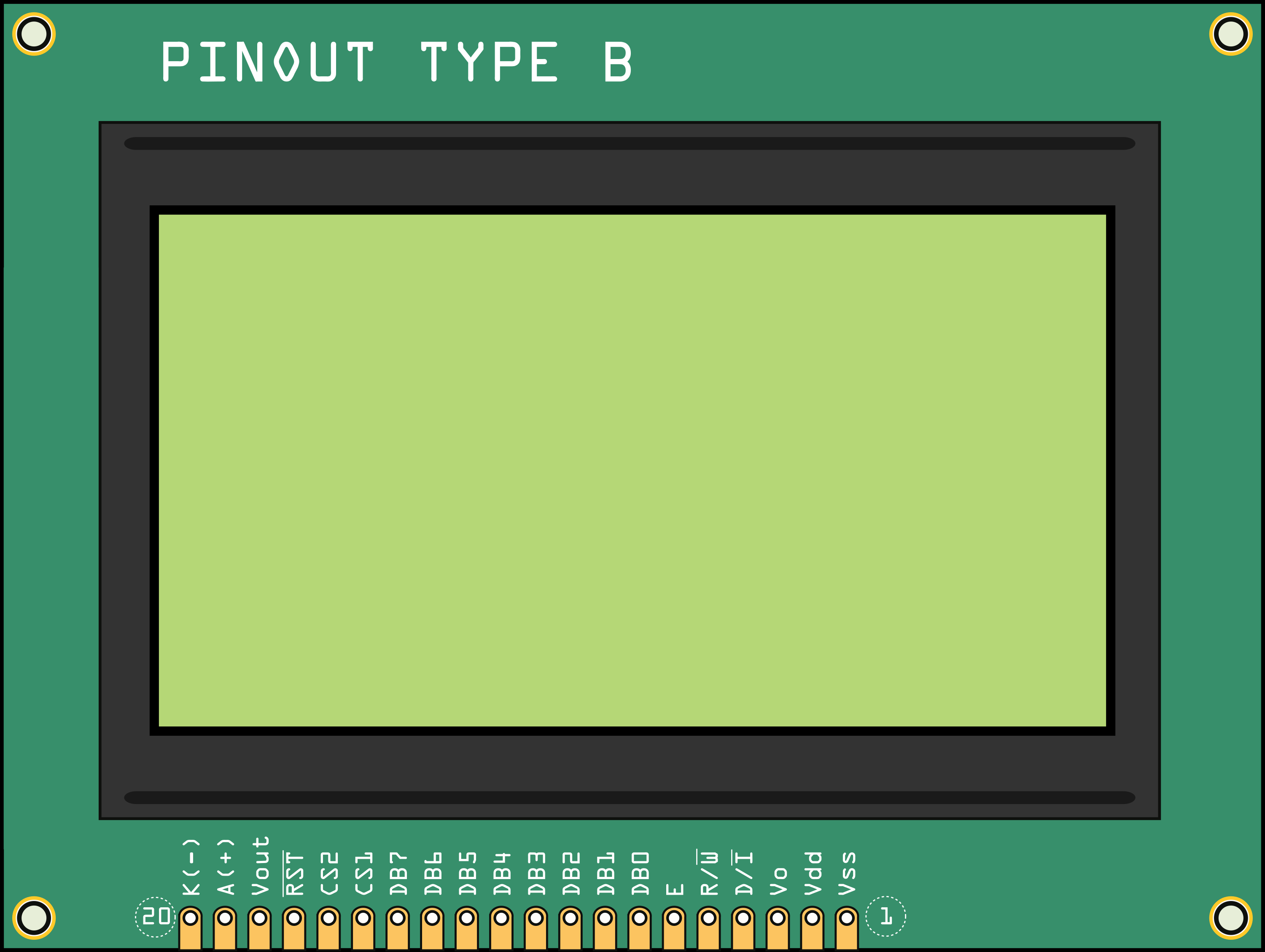
Pin Configuration and Descriptions
| Pin Number | Pin Name | Description |
|---|---|---|
| 1 | VSS | Ground |
| 2 | VDD | Power supply (5V) |
| 3 | VO | Contrast adjustment |
| 4 | RS | Register select |
| 5 | R/W | Read/Write select |
| 6 | E | Enable signal |
| 7-14 | DB0-DB7 | Data bus for 8-bit mode |
| 15 | CS1 | Chip select for the left half of the display |
| 16 | CS2 | Chip select for the right half of the display |
| 17 | RST | Reset signal |
| 18 | VOUT | LCD driving voltage output |
| 19 | BLA | Backlight anode |
| 20 | BLK | Backlight cathode |
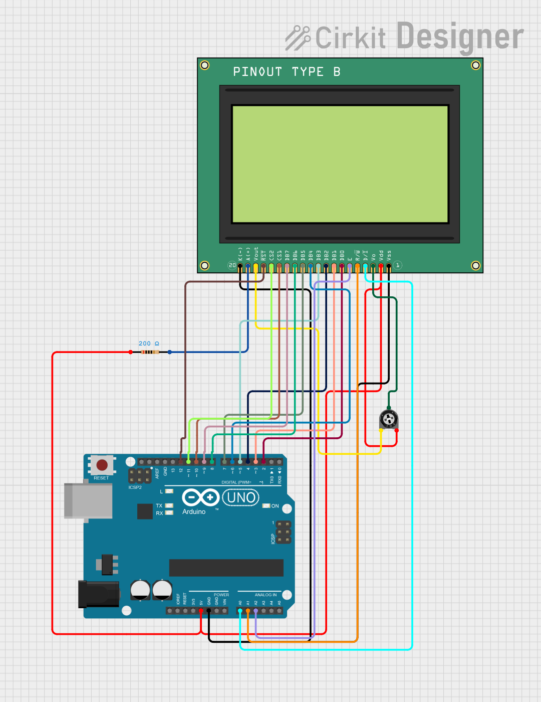
Usage Instructions
How to Use the Component in a Circuit
- Power Connections: Connect VSS to ground and VDD to a 5V supply.
- Contrast Adjustment: Connect VO to a potentiometer for contrast control.
- Data Interface: Connect DB0-DB7 to the microcontroller if using 8-bit mode.
- Control Pins: Connect RS, R/W, E, CS1, CS2, and RST to the microcontroller's digital output pins.
- Backlight: Connect BLA to 5V and BLK to ground, possibly through a current-limiting resistor.
Important Considerations and Best Practices
- Always ensure that the power supply is within the specified voltage range to prevent damage.
- Use a current-limiting resistor for the backlight to prevent excessive current draw.
- When writing to the display, ensure proper timing for the enable (E) signal to ensure data is correctly registered.
- Utilize the reset (RST) pin to initialize the display on startup.
- Adjust the contrast (VO) for optimal visibility under varying lighting conditions.
Example Code for Arduino UNO
#include <U8glib.h> // Include U8glib graphics library

// Constructor for the GLCD - modify based on the specific interface used
U8GLIB_ST7920_128X64_1X u8g(13, 11, 10, 9); // SPI Com: SCK = 13, MOSI = 11, CS = 10, A0 = 9

void setup() {
  // Initialize the GLCD
  u8g.begin();
}

void loop() {
  // Picture loop
  u8g.firstPage();
  do {
    draw();
  } while ( u8g.nextPage() );

  // Delay between each refresh
  delay(1000);
}

void draw() {
  // Graphic commands to draw to the screen
  // Draw a frame and string at x=0, y=30
  u8g.setFont(u8g_font_unifont);
  u8g.drawStr(0, 30, "Hello World!");
}
Troubleshooting and FAQs
Common Issues Users Might Face
- Display not powering on: Check the power connections and ensure the voltage is within the specified range.
- No display or weak contrast: Adjust the contrast potentiometer connected to VO.
- Garbled or partial display: Ensure that the CS1 and CS2 pins are correctly toggled for the respective halves of the display.
- Backlight not working: Verify the connections to BLA and BLK, and ensure there is a current-limiting resistor if necessary.
Solutions and Tips for Troubleshooting
- Double-check all wiring against the pin configuration table.
- Use example code to test the display functionality before integrating into a larger project.
- If using SPI, ensure that the SPI pins are correctly connected and that the library is properly initialized.
FAQs
Q: Can I use this display with a 3.3V system? A: While the GLCD is typically rated for 5V, some models may work with 3.3V logic. Check the datasheet for your specific model, and consider using level shifters if necessary.
Q: How do I control the backlight brightness? A: The backlight brightness can be controlled by applying a PWM signal to the BLA pin or by using a variable resistor.
Q: What library should I use for programming the GLCD with an Arduino? A: The U8glib library is commonly used for GLCDs and supports various models. Ensure you select the correct constructor for your display's interface.
Q: How can I display images on the GLCD? A: Images need to be converted to a bitmap array in the correct format. Tools are available online to convert images for use with GLCDs. Once converted, you can use the drawBitmap function provided by the library.