How to Use A02YYUW: Examples, Pinouts, and Specs
Introduction
The A02YYUW, manufactured by ESP32 S3, is a versatile electronic component commonly used in signal processing and power management applications. Its robust design and adaptability make it suitable for a wide range of electronic circuits, from consumer electronics to industrial systems. The exact functionality of the A02YYUW depends on the specific circuit design and application context, making it a valuable component for engineers and hobbyists alike.
Explore Projects Built with A02YYUW

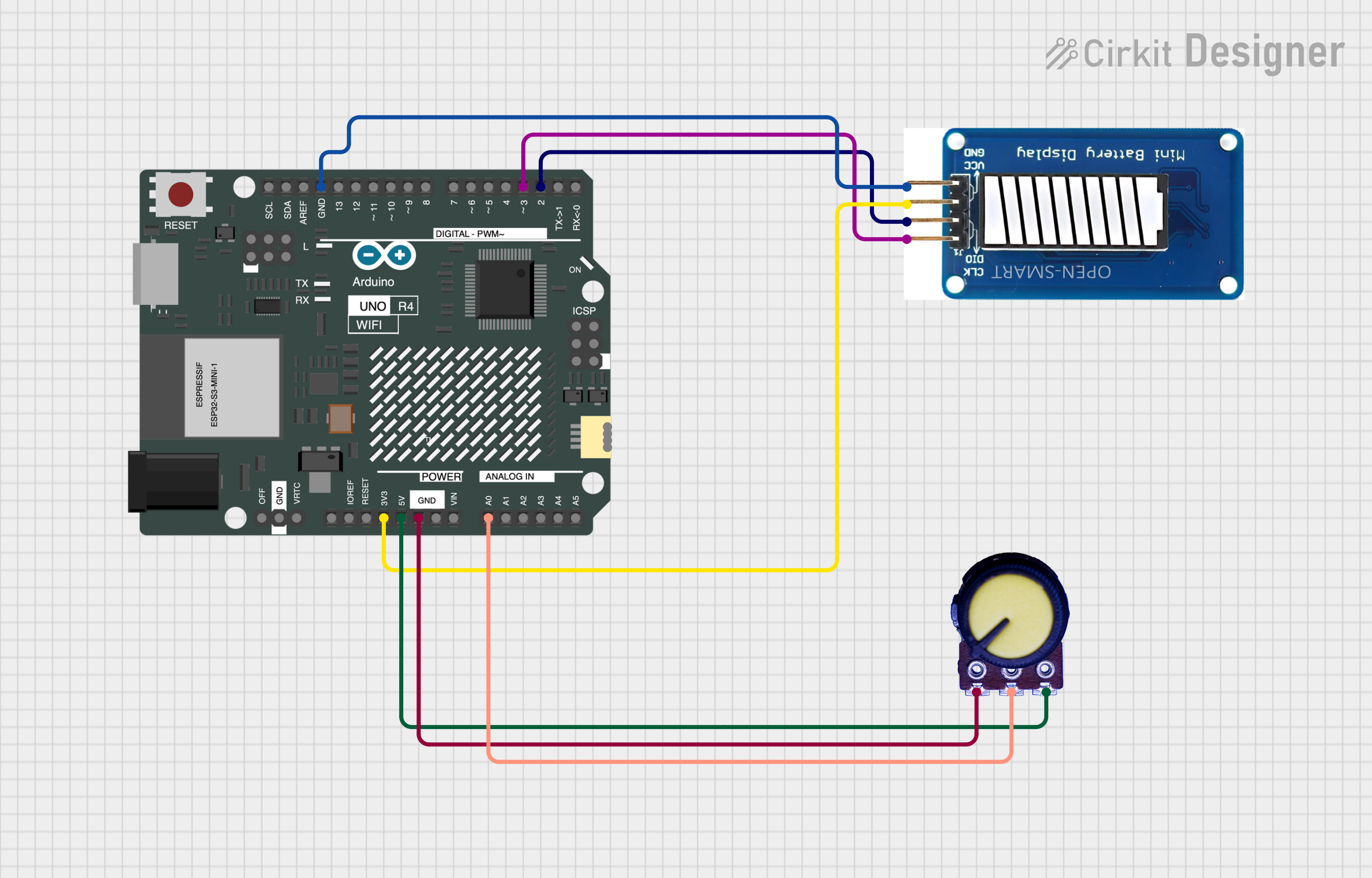

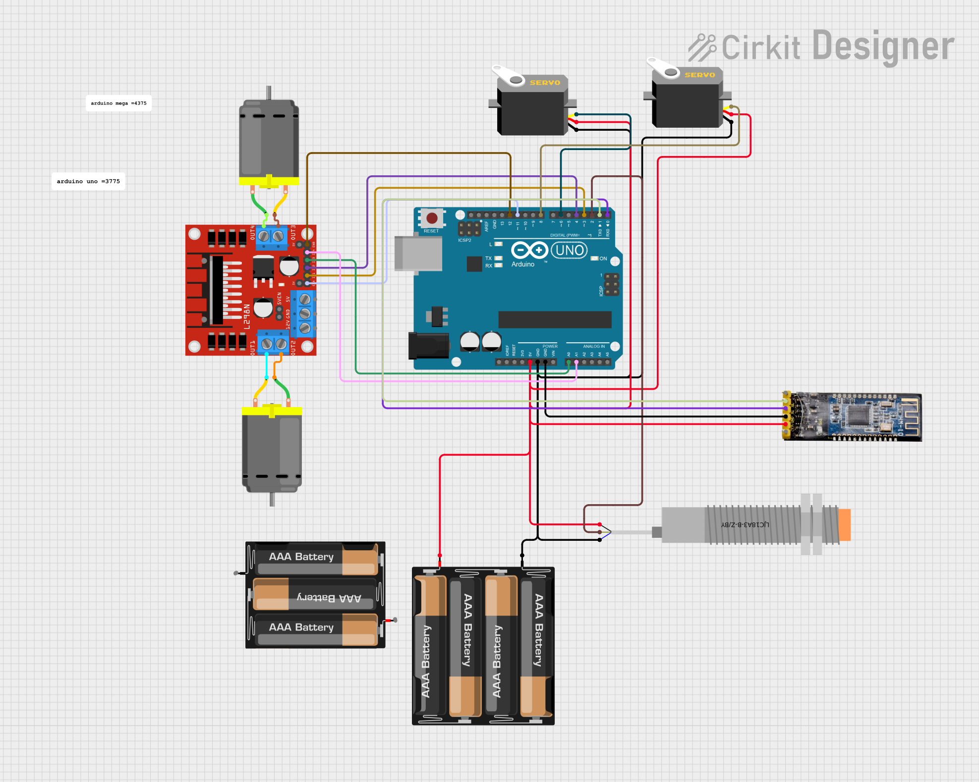
Explore Projects Built with A02YYUW
Common Applications
- Signal processing in communication systems
- Power management in embedded devices
- Voltage regulation in microcontroller-based circuits
- General-purpose use in prototyping and development boards
Technical Specifications
The A02YYUW is designed to operate efficiently under a variety of conditions. Below are its key technical specifications:
| Parameter | Value |
|---|---|
| Manufacturer | ESP32 S3 |
| Part ID | A02 |
| Operating Voltage | 3.3V to 5V |
| Maximum Current | 500mA |
| Power Dissipation | 1W |
| Operating Temperature | -40°C to +85°C |
| Package Type | Surface Mount (SMD) |
| Communication Protocol | I2C, SPI (if applicable) |
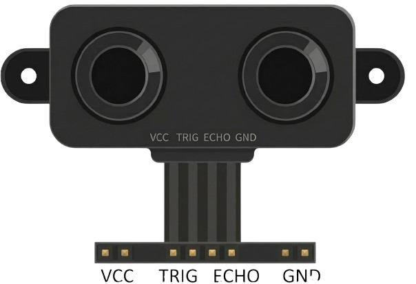
Pin Configuration
The A02YYUW features a standard pinout for easy integration into circuits. Below is the pin configuration:
| Pin Number | Pin Name | Description |
|---|---|---|
| 1 | VCC | Power supply input (3.3V to 5V) |
| 2 | GND | Ground connection |
| 3 | IN | Input signal or voltage |
| 4 | OUT | Output signal or regulated voltage |
| 5 | SCL | Serial Clock Line (for I2C, if used) |
| 6 | SDA | Serial Data Line (for I2C, if used) |
Usage Instructions
To use the A02YYUW in a circuit, follow these steps:
- Power Supply: Connect the VCC pin to a stable power source (3.3V to 5V) and the GND pin to the ground of your circuit.
- Input Signal: Provide the input signal or voltage to the IN pin. Ensure the input does not exceed the component's maximum ratings.
- Output Signal: The OUT pin will provide the processed or regulated output signal. Connect this pin to the desired load or circuit.
- Communication (Optional): If using I2C communication, connect the SCL and SDA pins to the corresponding pins on your microcontroller (e.g., Arduino UNO).
Example: Using A02YYUW with Arduino UNO
Below is an example of how to connect and use the A02YYUW with an Arduino UNO for signal processing:
Circuit Connections
- Connect the VCC pin of the A02YYUW to the 5V pin on the Arduino.
- Connect the GND pin of the A02YYUW to the GND pin on the Arduino.
- Connect the IN pin to an input signal source (e.g., a sensor).
- Connect the OUT pin to an analog input pin on the Arduino (e.g., A0).
- If using I2C, connect the SCL pin to A5 and the SDA pin to A4 on the Arduino UNO.
Arduino Code Example
// Example code for using A02YYUW with Arduino UNO
// This code reads the output signal from the A02YYUW and prints it to the Serial Monitor.

const int outputPin = A0; // Connect OUT pin of A02YYUW to A0 on Arduino

void setup() {
  Serial.begin(9600); // Initialize serial communication at 9600 baud
  pinMode(outputPin, INPUT); // Set the output pin as input
}

void loop() {
  int signalValue = analogRead(outputPin); // Read the signal from A02YYUW
  float voltage = (signalValue / 1023.0) * 5.0; // Convert to voltage (assuming 5V reference)

  // Print the signal value and voltage to the Serial Monitor
  Serial.print("Signal Value: ");
  Serial.print(signalValue);
  Serial.print(" | Voltage: ");
  Serial.println(voltage);

  delay(500); // Wait for 500ms before the next reading
}
Best Practices
- Ensure the input voltage and current do not exceed the component's maximum ratings to avoid damage.
- Use decoupling capacitors near the VCC and GND pins to stabilize the power supply.
- If using I2C, ensure proper pull-up resistors are connected to the SCL and SDA lines.
Troubleshooting and FAQs
Common Issues
No Output Signal:
- Check the power supply connections (VCC and GND).
- Verify that the input signal is within the specified range.
Erratic Output:
- Ensure proper grounding in the circuit.
- Add decoupling capacitors to filter noise from the power supply.
I2C Communication Failure:
- Verify the SCL and SDA connections.
- Check if pull-up resistors are correctly installed on the I2C lines.
FAQs
Q: Can the A02YYUW operate at 3.3V?
A: Yes, the A02YYUW supports an operating voltage range of 3.3V to 5V.
Q: Is the A02YYUW compatible with Arduino boards?
A: Yes, the A02YYUW can be easily interfaced with Arduino boards using analog or I2C connections.
Q: What is the maximum input signal the A02YYUW can handle?
A: Refer to the datasheet for the exact input signal range, but ensure it does not exceed the component's maximum ratings.
Q: How do I know if the component is damaged?
A: If the component does not produce an output signal despite correct connections and input, it may be damaged. Verify with a multimeter or oscilloscope.
By following this documentation, users can effectively integrate the A02YYUW into their projects and troubleshoot common issues.