
How to Use LM2576: Examples, Pinouts, and Specs
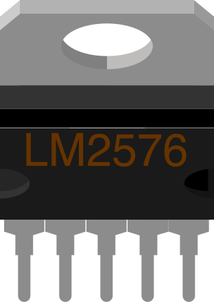
 Design with LM2576 in Cirkit Designer
Introduction
The LM2576, manufactured by Texas Instruments, is a step-down (buck) voltage regulator designed for efficient power conversion. It provides a fixed output voltage of 3.3V, 5V, or 12V, and is capable of delivering up to 3A of output current. This regulator is highly reliable, featuring built-in thermal shutdown, current limiting, and an efficient switching design that minimizes heat generation.
Explore Projects Built with LM2576
 Open Project in Cirkit Designer
 Open Project in Cirkit Designer
 Open Project in Cirkit Designer
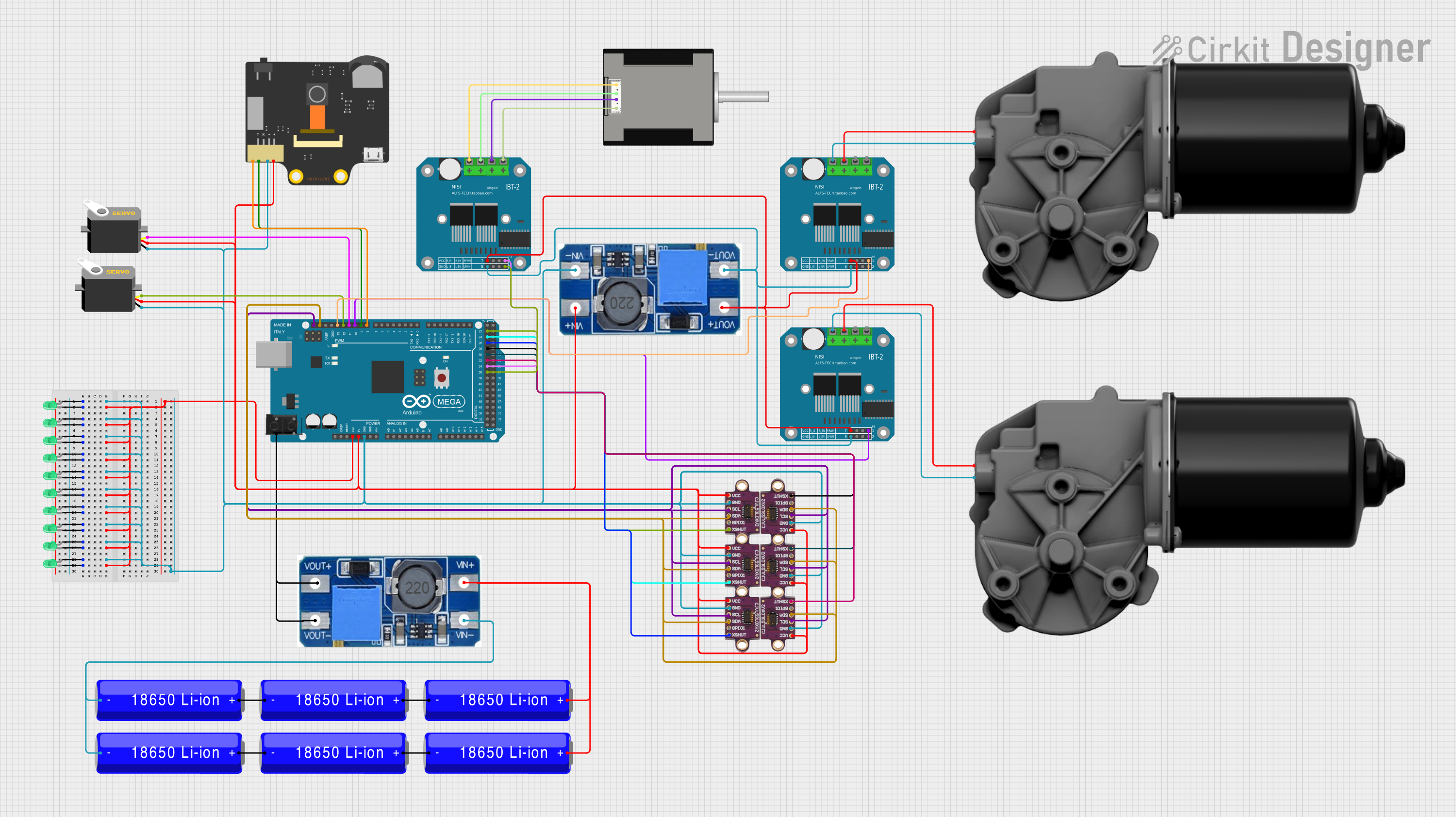 Open Project in Cirkit Designer
Explore Projects Built with LM2576
Open Project in Cirkit DesignerOpen Project in Cirkit DesignerOpen Project in Cirkit DesignerOpen Project in Cirkit DesignerCommon Applications and Use Cases
- Power supply for microcontrollers and embedded systems
- Battery-powered devices
- Industrial automation systems
- Consumer electronics
- DC-DC conversion in automotive applications
Technical Specifications
The LM2576 is designed to simplify power supply design while maintaining high efficiency and reliability. Below are its key technical specifications:
| Parameter | Value |
|---|---|
| Input Voltage Range | 4V to 40V |
| Output Voltage Options | 3.3V, 5V, 12V (fixed) or adjustable (1.23V to 37V) |
| Maximum Output Current | 3A |
| Efficiency | Up to 90% |
| Switching Frequency | 52 kHz (fixed) |
| Thermal Shutdown | Yes |
| Current Limiting | Yes |
| Package Options | TO-220, TO-263 |
Pin Configuration and Descriptions
The LM2576 is available in a 5-pin package. Below is the pinout and description:
| Pin Number | Pin Name | Description |
|---|---|---|
| 1 | VIN | Input voltage pin. Connect to the unregulated DC input voltage. |
| 2 | OUTPUT | Regulated output voltage pin. Connect to the load. |
| 3 | GND | Ground pin. Connect to the system ground. |
| 4 | FEEDBACK | Feedback pin. Used to set the output voltage (for adjustable version). |
| 5 | ON/OFF | Enable/disable pin. Logic high disables the regulator; logic low enables it. |
Usage Instructions
The LM2576 is straightforward to use in a circuit. Below are the steps and considerations for proper usage:
Basic Circuit Design
- Input Capacitor: Place a capacitor (typically 100 µF electrolytic) close to the VIN pin to stabilize the input voltage.
- Output Capacitor: Use a low-ESR capacitor (e.g., 330 µF electrolytic) at the OUTPUT pin to ensure stable operation.
- Inductor Selection: Choose an inductor with a current rating higher than the maximum load current (e.g., 3.5A) and an appropriate inductance value (e.g., 68 µH for 5V output).
- Diode Selection: Use a Schottky diode (e.g., 1N5822) for fast switching and low forward voltage drop.
- Feedback Resistors (Adjustable Version): For the adjustable version, use a resistor divider network to set the desired output voltage.
Example Circuit
Below is a typical application circuit for the LM2576 (5V fixed output version):
VIN (12V) ----+---- Input Capacitor (100 µF) ----+---- VIN (Pin 1)
              |                                  |
              +---- Inductor (68 µH) ----+---- OUTPUT (Pin 2)
                                         |
                                         +---- Output Capacitor (330 µF)
                                         |
                                         +---- Load
Arduino UNO Example (Adjustable Version)
The LM2576 can be used to power an Arduino UNO. Below is an example of how to connect it:
- Connect the VIN pin of the LM2576 to a 12V DC power source.
- Set the output voltage to 5V using the feedback resistors.
- Connect the OUTPUT pin to the Arduino UNO's 5V pin.
Sample Code for Arduino UNO
// Example code to blink an LED using Arduino UNO powered by LM2576
// Ensure the LM2576 output is set to 5V before connecting to the Arduino.

const int ledPin = 13; // Pin connected to the onboard LED

void setup() {
  pinMode(ledPin, OUTPUT); // Set the LED pin as an output
}

void loop() {
  digitalWrite(ledPin, HIGH); // Turn the LED on
  delay(1000);                // Wait for 1 second
  digitalWrite(ledPin, LOW);  // Turn the LED off
  delay(1000);                // Wait for 1 second
}
Best Practices
- Always use low-ESR capacitors for stable operation.
- Ensure proper heat dissipation by using a heatsink if the regulator operates near its maximum current rating.
- Keep the input and output capacitor connections as close as possible to the LM2576 pins to minimize noise.
- Use a PCB layout with a solid ground plane for optimal performance.
Troubleshooting and FAQs
Common Issues and Solutions
Output Voltage is Incorrect
- Cause: Incorrect feedback resistor values (adjustable version) or insufficient input voltage.
- Solution: Verify the resistor values and ensure the input voltage is at least 3V higher than the desired output voltage.
Regulator Overheats
- Cause: Excessive load current or insufficient heat dissipation.
- Solution: Reduce the load current or attach a heatsink to the LM2576.
High Output Ripple
- Cause: Poor capacitor selection or layout issues.
- Solution: Use low-ESR capacitors and ensure proper PCB layout with short traces.
No Output Voltage
- Cause: ON/OFF pin is not properly connected or input voltage is too low.
- Solution: Ensure the ON/OFF pin is connected to ground (logic low) and check the input voltage.
FAQs
Q1: Can the LM2576 be used for negative voltage regulation?
A1: Yes, the LM2576-NEG version is specifically designed for negative voltage regulation.
Q2: What is the maximum input voltage for the LM2576?
A2: The maximum input voltage is 40V.
Q3: Can I use the LM2576 without an inductor?
A3: No, an inductor is essential for the buck converter operation and must be included in the circuit.
Q4: How do I calculate the feedback resistor values for the adjustable version?
A4: Use the formula:
[
V_{OUT} = V_{REF} \times \left(1 + \frac{R_2}{R_1}\right)
]
where ( V_{REF} = 1.23V ), ( R_1 ) is connected between the feedback pin and ground, and ( R_2 ) is connected between the output and feedback pin.
By following this documentation, users can effectively integrate the LM2576 into their designs for efficient and reliable power regulation.