Cirkit Designer Logo
Cirkit Designer
Your all-in-one circuit design IDE
Home / 
Component Documentation

How to Use PN5180: Examples, Pinouts, and Specs

Image of PN5180
Cirkit Designer LogoDesign with PN5180 in Cirkit Designer

Introduction

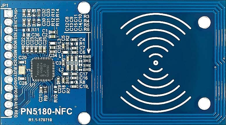
The PN5180 is a highly integrated NFC (Near Field Communication) reader IC designed for contactless communication. It supports various NFC protocols, including ISO/IEC 14443, ISO/IEC 15693, and FeliCa, making it a versatile solution for a wide range of NFC applications. The PN5180 is optimized for high performance and low power consumption, making it suitable for mobile payments, access control systems, smart card readers, and other NFC-enabled devices.

Explore Projects Built with PN5180

Use Cirkit Designer to design, explore, and prototype these projects online. Some projects support real-time simulation. Click "Open Project" to start designing instantly!
Satellite Compass and Network-Integrated GPS Data Processing System
Image of GPS 시스템 측정 구성도_241016: A project utilizing PN5180 in a practical application
This circuit comprises a satellite compass, a mini PC, two GPS antennas, power supplies, a network switch, media converters, and an atomic rubidium clock. The satellite compass is powered by a triple output DC power supply and interfaces with an RS232 splitter for 1PPS signals. The mini PCs are connected to the USRP B200 devices via USB for data and power, and to media converters via Ethernet, which in turn connect to a network switch using fiber optic links. The antennas are connected to the USRP B200s through RF directional couplers, and the atomic clock provides a 1PPS input to the RS232 splitter.
Cirkit Designer LogoOpen Project in Cirkit Designer
Satellite-Based Timing and Navigation System with SDR and Atomic Clock Synchronization
Image of GPS 시스템 측정 구성도_Confirm: A project utilizing PN5180 in a practical application
This circuit appears to be a complex system involving power supply management, GPS and timing synchronization, and data communication. It includes a SI-TEX G1 Satellite Compass for GPS data, an XHTF1021 Atomic Rubidium Clock for precise timing, and Ettus USRP B200 units for software-defined radio communication. Power is supplied through various SMPS units and distributed via terminal blocks and DC jacks. Data communication is facilitated by Beelink MINI S12 N95 computers, RS232 splitters, and a 1000BASE-T Media Converter for network connectivity. RF Directional Couplers are used to interface antennas with the USRP units, and the entire system is likely contained within cases for protection and organization.
Cirkit Designer LogoOpen Project in Cirkit Designer
Battery-Powered Emergency Alert System with NUCLEO-F072RB, SIM800L, and GPS NEO 6M
Image of women safety: A project utilizing PN5180 in a practical application
This circuit is an emergency alert system that uses a NUCLEO-F072RB microcontroller to send SMS alerts and make calls via a SIM800L GSM module, while obtaining location data from a GPS NEO 6M module. The system is powered by a Li-ion battery and includes a TP4056 module for battery charging and protection, with a rocker switch to control power to the microcontroller.
Cirkit Designer LogoOpen Project in Cirkit Designer
Battery-Powered Raspberry Pi Pico GPS Tracker with Sensor Integration
Image of Copy of CanSet v1: A project utilizing PN5180 in a practical application
This circuit is a data acquisition and communication system powered by a LiPoly battery and managed by a Raspberry Pi Pico. It includes sensors (BMP280, MPU9250) for environmental data, a GPS module for location tracking, an SD card for data storage, and a WLR089-CanSAT for wireless communication. The TP4056 module handles battery charging, and a toggle switch controls power distribution.
Cirkit Designer LogoOpen Project in Cirkit Designer

Explore Projects Built with PN5180

Use Cirkit Designer to design, explore, and prototype these projects online. Some projects support real-time simulation. Click "Open Project" to start designing instantly!
Image of GPS 시스템 측정 구성도_241016: A project utilizing PN5180 in a practical application
Satellite Compass and Network-Integrated GPS Data Processing System
This circuit comprises a satellite compass, a mini PC, two GPS antennas, power supplies, a network switch, media converters, and an atomic rubidium clock. The satellite compass is powered by a triple output DC power supply and interfaces with an RS232 splitter for 1PPS signals. The mini PCs are connected to the USRP B200 devices via USB for data and power, and to media converters via Ethernet, which in turn connect to a network switch using fiber optic links. The antennas are connected to the USRP B200s through RF directional couplers, and the atomic clock provides a 1PPS input to the RS232 splitter.
Cirkit Designer LogoOpen Project in Cirkit Designer
Image of GPS 시스템 측정 구성도_Confirm: A project utilizing PN5180 in a practical application
Satellite-Based Timing and Navigation System with SDR and Atomic Clock Synchronization
This circuit appears to be a complex system involving power supply management, GPS and timing synchronization, and data communication. It includes a SI-TEX G1 Satellite Compass for GPS data, an XHTF1021 Atomic Rubidium Clock for precise timing, and Ettus USRP B200 units for software-defined radio communication. Power is supplied through various SMPS units and distributed via terminal blocks and DC jacks. Data communication is facilitated by Beelink MINI S12 N95 computers, RS232 splitters, and a 1000BASE-T Media Converter for network connectivity. RF Directional Couplers are used to interface antennas with the USRP units, and the entire system is likely contained within cases for protection and organization.
Cirkit Designer LogoOpen Project in Cirkit Designer
Image of women safety: A project utilizing PN5180 in a practical application
Battery-Powered Emergency Alert System with NUCLEO-F072RB, SIM800L, and GPS NEO 6M
This circuit is an emergency alert system that uses a NUCLEO-F072RB microcontroller to send SMS alerts and make calls via a SIM800L GSM module, while obtaining location data from a GPS NEO 6M module. The system is powered by a Li-ion battery and includes a TP4056 module for battery charging and protection, with a rocker switch to control power to the microcontroller.
Cirkit Designer LogoOpen Project in Cirkit Designer
Image of Copy of CanSet v1: A project utilizing PN5180 in a practical application
Battery-Powered Raspberry Pi Pico GPS Tracker with Sensor Integration
This circuit is a data acquisition and communication system powered by a LiPoly battery and managed by a Raspberry Pi Pico. It includes sensors (BMP280, MPU9250) for environmental data, a GPS module for location tracking, an SD card for data storage, and a WLR089-CanSAT for wireless communication. The TP4056 module handles battery charging, and a toggle switch controls power distribution.
Cirkit Designer LogoOpen Project in Cirkit Designer

Common Applications and Use Cases

  • Mobile payment terminals
  • Access control systems
  • Smart card readers
  • Ticketing systems
  • NFC-enabled IoT devices
  • Industrial automation with NFC communication

Technical Specifications

Key Technical Details

  • Operating Voltage: 3.0V to 5.5V
  • Operating Frequency: 13.56 MHz
  • Supported Protocols: ISO/IEC 14443 A/B, ISO/IEC 15693, FeliCa, MIFARE
  • Host Interface: SPI (Serial Peripheral Interface)
  • Power Consumption: Low-power modes available for energy-efficient operation
  • Output Power: Up to 1.3W (adjustable)
  • Temperature Range: -30°C to +85°C
  • Package: HVQFN32 (32-pin)

Pin Configuration and Descriptions

The PN5180 comes in a 32-pin HVQFN package. Below is the pin configuration and description:

Pin Number Pin Name Description
1 VDD Power supply input (3.0V to 5.5V).
2 GND Ground connection.
3 TX1 Transmitter output 1 for antenna connection.
4 TX2 Transmitter output 2 for antenna connection.
5 RX Receiver input for antenna signal.
6 IRQ Interrupt request output to signal events to the host.
7 NSS SPI chip select (active low).
8 MOSI SPI Master Out Slave In (data input to PN5180).
9 MISO SPI Master In Slave Out (data output from PN5180).
10 SCK SPI clock input.
11 RST Reset input (active low).
12-31 NC Not connected (reserved for future use).
32 AUX1 Auxiliary pin for additional functionality (e.g., debugging or custom features).

Usage Instructions

How to Use the PN5180 in a Circuit

  1. Power Supply: Connect the VDD pin to a stable power source (3.0V to 5.5V) and GND to the ground.
  2. Antenna Connection: Connect the TX1 and TX2 pins to an NFC antenna. Ensure proper impedance matching for optimal performance.
  3. SPI Communication: Connect the SPI pins (NSS, MOSI, MISO, SCK) to the host microcontroller. Configure the SPI interface on the host to communicate with the PN5180.
  4. Interrupt Handling: Use the IRQ pin to detect events such as tag detection or communication errors.
  5. Reset: Use the RST pin to reset the PN5180 when needed.

Important Considerations and Best Practices

  • Antenna Design: Proper antenna design and tuning are critical for achieving optimal NFC performance. Use the PN5180 antenna design guide provided by the manufacturer.
  • Decoupling Capacitors: Place decoupling capacitors close to the VDD pin to ensure stable operation.
  • Firmware Updates: Ensure the host microcontroller has the latest firmware to support the PN5180.
  • ESD Protection: Implement ESD protection on the antenna and communication lines to prevent damage.

Example Code for Arduino UNO

Below is an example of how to interface the PN5180 with an Arduino UNO using SPI:

#include <SPI.h>

// Define PN5180 SPI pins
#define PN5180_NSS 10  // Chip select pin
#define PN5180_RST 9   // Reset pin
#define PN5180_IRQ 2   // Interrupt pin

void setup() {
  // Initialize serial communication for debugging
  Serial.begin(9600);
  Serial.println("Initializing PN5180...");

  // Initialize SPI
  SPI.begin();
  pinMode(PN5180_NSS, OUTPUT);
  pinMode(PN5180_RST, OUTPUT);
  pinMode(PN5180_IRQ, INPUT);

  // Reset the PN5180
  digitalWrite(PN5180_RST, LOW);
  delay(50); // Hold reset for 50ms
  digitalWrite(PN5180_RST, HIGH);
  delay(50); // Wait for the PN5180 to initialize

  Serial.println("PN5180 initialized.");
}

void loop() {
  // Example: Check for IRQ signal
  if (digitalRead(PN5180_IRQ) == HIGH) {
    Serial.println("PN5180 IRQ triggered!");
    // Add code to handle NFC events
  }

  delay(100); // Small delay to avoid spamming the serial monitor
}

Troubleshooting and FAQs

Common Issues and Solutions

  1. No Response from PN5180

    • Cause: Incorrect SPI connection or configuration.
    • Solution: Verify the SPI wiring and ensure the host microcontroller is configured for SPI communication.
  2. Poor NFC Range

    • Cause: Improper antenna design or tuning.
    • Solution: Check the antenna design and ensure it is tuned according to the PN5180 design guidelines.
  3. High Power Consumption

    • Cause: PN5180 not entering low-power mode.
    • Solution: Implement power-saving features in the firmware and ensure unused features are disabled.
  4. Intermittent Communication Errors

    • Cause: Noise or interference on SPI lines.
    • Solution: Use shorter wires for SPI connections and add pull-up resistors if necessary.

FAQs

  • Q: Can the PN5180 read multiple NFC tags simultaneously?
    A: The PN5180 supports anti-collision protocols, allowing it to detect and communicate with multiple tags sequentially.

  • Q: Is the PN5180 compatible with Arduino libraries?
    A: Yes, there are third-party libraries available for interfacing the PN5180 with Arduino. Ensure the library supports your specific use case.

  • Q: What is the maximum NFC range of the PN5180?
    A: The range depends on the antenna design and environmental factors but typically ranges from 5 to 10 cm.

  • Q: Does the PN5180 support peer-to-peer NFC communication?
    A: Yes, the PN5180 supports peer-to-peer communication as per the NFC Forum specifications.