How to Use OLED SEEED 96×96 (SSD1327): Examples, Pinouts, and Specs
Introduction
The OLED SEEED 96×96 (SKU 104030011) is a compact, low-power OLED display module manufactured by SEEED. It features a resolution of 96x96 pixels and is driven by the SSD1327 controller. This display is ideal for applications requiring a small, high-contrast visual output, such as wearable devices, IoT projects, and embedded systems.
Explore Projects Built with OLED SEEED 96×96 (SSD1327)


Explore Projects Built with OLED SEEED 96×96 (SSD1327)
Common Applications and Use Cases
- Wearable devices and smart gadgets
- IoT dashboards and status indicators
- Compact user interfaces for embedded systems
- Graphical data visualization in portable devices
- Educational and hobbyist electronics projects
Technical Specifications
The following table outlines the key technical details of the OLED SEEED 96×96 display:
| Parameter | Value |
|---|---|
| Manufacturer | SEEED |
| Manufacturer Part ID | SKU 104030011 |
| Display Type | OLED |
| Resolution | 96x96 pixels |
| Controller | SSD1327 |
| Interface | I2C |
| Operating Voltage | 3.3V to 5V |
| Operating Current | ~10mA (typical) |
| Dimensions | 26.7mm x 26.7mm |
| Pixel Color Depth | 4-bit grayscale (16 levels) |
| Viewing Angle | >160° |
| Operating Temperature | -40°C to +85°C |
Pin Configuration and Descriptions
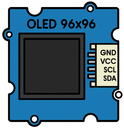
The OLED SEEED 96×96 module has a 4-pin interface for I2C communication. The pinout is as follows:
| Pin | Name | Description |
|---|---|---|
| 1 | GND | Ground connection |
| 2 | VCC | Power supply (3.3V to 5V) |
| 3 | SCL | I2C clock line |
| 4 | SDA | I2C data line |
Usage Instructions
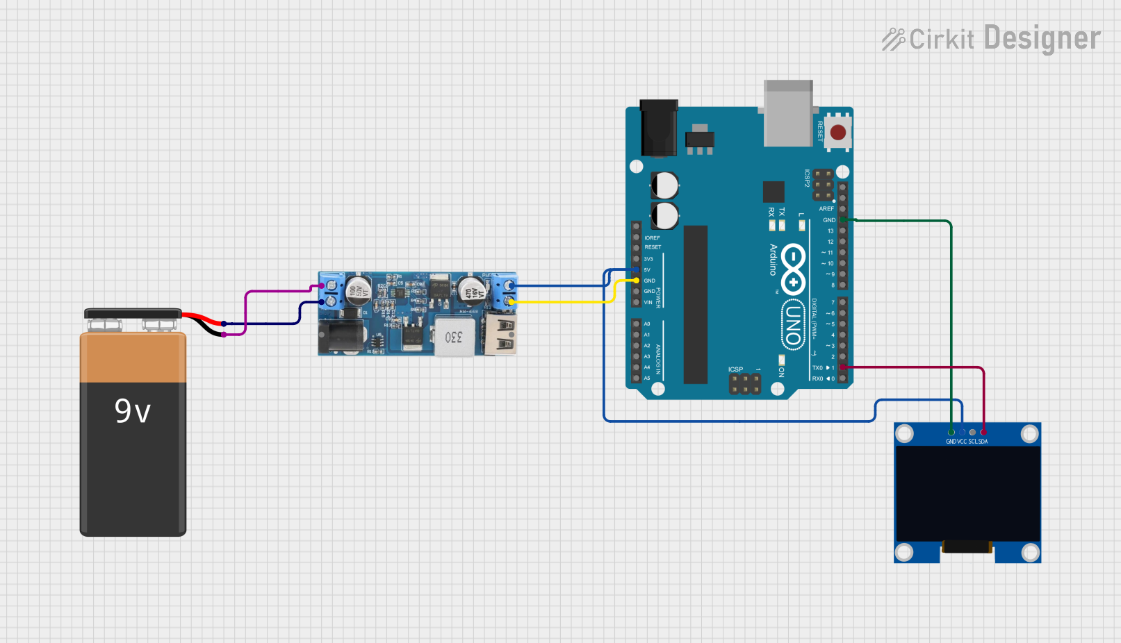
How to Use the Component in a Circuit
- Power Supply: Connect the
VCCpin to a 3.3V or 5V power source and theGNDpin to ground. - I2C Communication: Connect the
SCLandSDApins to the corresponding I2C pins on your microcontroller. For an Arduino UNO:SCLconnects to A5.SDAconnects to A4.
- Pull-Up Resistors: Ensure that the I2C lines (SCL and SDA) have pull-up resistors (typically 4.7kΩ to 10kΩ) if not already present on the module.
Important Considerations and Best Practices
- Voltage Compatibility: Ensure the microcontroller's I2C pins are compatible with the display's voltage levels (3.3V or 5V).
- I2C Address: The default I2C address of the SSD1327 controller is
0x3D. Verify this in your code or datasheet. - Initialization: Properly initialize the SSD1327 controller in your code before sending data to the display.
- Grayscale Rendering: The display supports 4-bit grayscale, allowing for 16 levels of brightness per pixel.
Example Code for Arduino UNO
Below is an example of how to use the OLED SEEED 96×96 display with an Arduino UNO. This code uses the Adafruit SSD1327 library.
#include <Wire.h>
#include <Adafruit_GFX.h>
#include <Adafruit_SSD1327.h>

// Define the I2C address for the SSD1327 display
#define SCREEN_ADDRESS 0x3D

// Create an instance of the SSD1327 display
Adafruit_SSD1327 display(96, 96, &Wire);

void setup() {
  // Initialize serial communication for debugging
  Serial.begin(9600);
  Serial.println("Initializing OLED...");

  // Initialize the display
  if (!display.begin(SSD1327_I2C_ADDRESS, SCREEN_ADDRESS)) {
    Serial.println("SSD1327 initialization failed!");
    while (1); // Halt execution if initialization fails
  }

  // Clear the display buffer
  display.clearDisplay();

  // Display a welcome message
  display.setTextSize(1); // Set text size to 1
  display.setTextColor(SSD1327_WHITE); // Set text color to white
  display.setCursor(0, 0); // Set cursor to top-left corner
  display.println("SEEED OLED 96x96");
  display.println("SSD1327 Example");
  display.display(); // Update the display with the buffer content
  delay(2000); // Wait for 2 seconds
}

void loop() {
  // Clear the display buffer
  display.clearDisplay();

  // Draw a rectangle
  display.drawRect(10, 10, 76, 76, SSD1327_WHITE);

  // Draw a filled circle
  display.fillCircle(48, 48, 20, SSD1327_WHITE);

  // Update the display with the buffer content
  display.display();

  // Wait for 1 second before refreshing
  delay(1000);
}
Troubleshooting and FAQs
Common Issues and Solutions
Display Not Turning On:
- Verify the power supply connections (
VCCandGND). - Ensure the I2C address in the code matches the display's default address (
0x3D).
- Verify the power supply connections (
No Output on the Display:
- Check the I2C connections (
SCLandSDA) and ensure they are correctly wired. - Confirm that pull-up resistors are present on the I2C lines.
- Check the I2C connections (
Flickering or Unstable Display:
- Ensure a stable power supply with sufficient current capacity.
- Check for loose or poor-quality connections.
Grayscale Rendering Issues:
- Ensure the library and code properly support 4-bit grayscale rendering.
FAQs
Q: Can I use this display with a 3.3V microcontroller?
A: Yes, the OLED SEEED 96×96 is compatible with both 3.3V and 5V systems.
Q: What is the maximum frame rate of the display?
A: The SSD1327 controller supports a frame rate of up to 100Hz, depending on the configuration.
Q: Does the display require an external backlight?
A: No, OLED displays are self-emissive and do not require a backlight.
Q: Can I use this display with platforms other than Arduino?
A: Yes, the display can be used with any platform that supports I2C communication, such as Raspberry Pi, ESP32, and STM32.
Q: How do I change the I2C address of the display?
A: The I2C address is fixed at 0x3D for this module and cannot be changed.