How to Use Solar Power Manager 3.3/5/9/12V: Examples, Pinouts, and Specs
Introduction
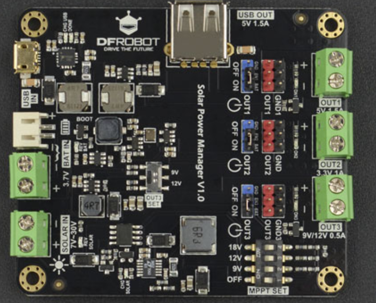
The Solar Power Manager 3.3/5/9/12V by DFRobot (Part ID: MPPT) is a versatile power management module designed to efficiently regulate and distribute solar energy. It supports multiple output voltages (3.3V, 5V, 9V, and 12V), making it suitable for a wide range of electronic applications. This module integrates Maximum Power Point Tracking (MPPT) technology to optimize solar energy harvesting, ensuring maximum efficiency.
Explore Projects Built with Solar Power Manager 3.3/5/9/12V

Explore Projects Built with Solar Power Manager 3.3/5/9/12V
Common Applications and Use Cases
- Powering IoT devices and sensors in remote locations
- Solar-powered battery charging systems
- Renewable energy projects and prototypes
- Portable solar energy solutions for outdoor electronics
- Educational projects involving solar energy and power management
Technical Specifications
The following table outlines the key technical details of the Solar Power Manager:
| Parameter | Value |
|---|---|
| Input Voltage Range | 6V to 24V (solar panel or DC input) |
| Output Voltages | 3.3V, 5V, 9V, 12V |
| Output Current (Max) | 1.5A (5V output), 1A (9V/12V outputs) |
| MPPT Efficiency | Up to 95% |
| Battery Charging Voltage | 4.2V (for single-cell Li-ion/LiPo batteries) |
| Battery Charging Current | 1A (default, adjustable via resistor) |
| Operating Temperature | -40°C to 85°C |
| Dimensions | 60mm x 50mm x 15mm |
Pin Configuration and Descriptions
The module features multiple input/output pins and connectors. The table below provides details:
| Pin/Connector | Type | Description |
|---|---|---|
| VIN | Input | Connect to a solar panel or DC power source (6V to 24V). |
| BAT | Input/Output | Connect to a single-cell Li-ion/LiPo battery for charging and discharging. |
| 3.3V | Output | Regulated 3.3V output for low-power devices. |
| 5V | Output | Regulated 5V output for standard electronic devices. |
| 9V | Output | Regulated 9V output for medium-power devices. |
| 12V | Output | Regulated 12V output for high-power devices. |
| GND | Ground | Common ground for all inputs and outputs. |
| EN | Input | Enable pin to turn the module on/off (active high). |
| STAT | Output | Status indicator pin for battery charging (low = charging, high = fully charged). |
Usage Instructions
How to Use the Component in a Circuit
Connect the Solar Panel or DC Input:
- Attach a solar panel (6V to 24V) to the
VINpin or connector. - Alternatively, connect a DC power source within the same voltage range.
- Attach a solar panel (6V to 24V) to the
Connect a Battery (Optional):
- Attach a single-cell Li-ion/LiPo battery to the
BATpin for charging and energy storage.
- Attach a single-cell Li-ion/LiPo battery to the
Select the Desired Output Voltage:
- Use the
3.3V,5V,9V, or12Voutput pins to power your devices. - Ensure the connected load does not exceed the maximum current rating for the selected output.
- Use the
Enable the Module:
- Use the
ENpin to enable or disable the module. Pull the pin high to enable the outputs.
- Use the
Monitor the Charging Status:
- Use the
STATpin to monitor the battery charging status. A low signal indicates charging, while a high signal indicates the battery is fully charged.
- Use the
Important Considerations and Best Practices
- MPPT Optimization: Ensure the solar panel operates within its optimal voltage and current range for maximum efficiency.
- Battery Protection: Use a compatible single-cell Li-ion/LiPo battery with built-in protection circuitry to prevent overcharging or deep discharge.
- Heat Dissipation: Avoid placing the module in enclosed spaces without ventilation, as it may generate heat during operation.
- Load Current: Do not exceed the maximum current rating for each output voltage to prevent damage to the module.
Example: Using with an Arduino UNO
The Solar Power Manager can be used to power an Arduino UNO via its 5V output. Below is an example setup and code:
Circuit Setup
- Connect the
5Voutput of the Solar Power Manager to the5Vpin of the Arduino UNO. - Connect the
GNDpin of the Solar Power Manager to theGNDpin of the Arduino UNO. - Optionally, connect a solar panel and battery to the module for a complete solar-powered system.
Example Code
// Example code to read a sensor and send data via serial
// Powered by the Solar Power Manager 5V output

const int sensorPin = A0; // Analog pin connected to the sensor
int sensorValue = 0;      // Variable to store the sensor reading

void setup() {
  Serial.begin(9600); // Initialize serial communication at 9600 baud
  pinMode(sensorPin, INPUT); // Set the sensor pin as input
}

void loop() {
  sensorValue = analogRead(sensorPin); // Read the sensor value
  Serial.print("Sensor Value: ");      // Print label to serial monitor
  Serial.println(sensorValue);         // Print the sensor value
  delay(1000);                         // Wait for 1 second before next reading
}
Troubleshooting and FAQs
Common Issues and Solutions
No Output Voltage:
- Cause: The
ENpin is not pulled high. - Solution: Ensure the
ENpin is connected to a high signal to enable the module.
- Cause: The
Battery Not Charging:
- Cause: Incompatible or faulty battery.
- Solution: Verify the battery is a single-cell Li-ion/LiPo type and is functioning properly.
Overheating:
- Cause: Excessive load or poor ventilation.
- Solution: Reduce the load current or improve ventilation around the module.
Low Efficiency:
- Cause: Solar panel not operating at its optimal point.
- Solution: Use a solar panel with a voltage and current rating suitable for the module's MPPT range.
FAQs
Can I use this module without a battery? Yes, the module can operate directly from a solar panel or DC input without a battery.
What happens if the input voltage exceeds 24V? The module may be damaged. Always ensure the input voltage stays within the specified range.
Can I adjust the battery charging current? Yes, the charging current can be adjusted by replacing the onboard resistor. Refer to the DFRobot datasheet for details.
Is the module compatible with other microcontrollers? Yes, the module can power any microcontroller that operates within the supported output voltages.