
How to Use LCD Display (16 pin): Examples, Pinouts, and Specs
 Design with LCD Display (16 pin) in Cirkit Designer
Introduction
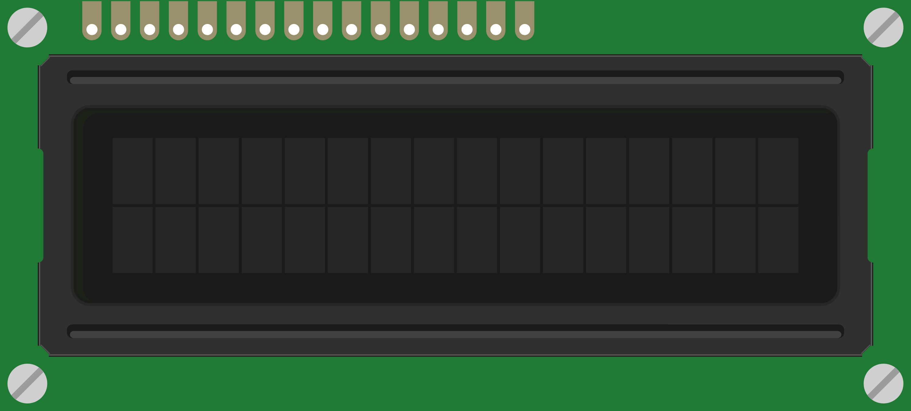
The 16-pin Liquid Crystal Display (LCD) is a versatile electronic component designed for displaying alphanumeric characters and simple graphics. It is widely used in embedded systems, microcontroller-based projects, and user interfaces due to its ease of use and low power consumption. This LCD operates in 4-bit or 8-bit modes, making it compatible with a variety of microcontrollers, including the Arduino UNO.
Common applications include:
- Digital clocks and timers
- Home automation systems
- Measurement instruments
- User interfaces for embedded systems
Explore Projects Built with LCD Display (16 pin)
 Open Project in Cirkit Designer
 Open Project in Cirkit Designer
 Open Project in Cirkit Designer
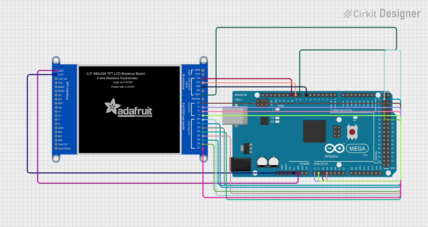 Open Project in Cirkit Designer
Explore Projects Built with LCD Display (16 pin)
Open Project in Cirkit DesignerOpen Project in Cirkit DesignerOpen Project in Cirkit DesignerOpen Project in Cirkit DesignerTechnical Specifications
The following are the key technical details of the 16-pin LCD display:
| Parameter | Value |
|---|---|
| Operating Voltage | 4.7V to 5.3V |
| Operating Current | 1mA to 2mA (without backlight) |
| Backlight Voltage | 4.2V to 4.6V |
| Backlight Current | 10mA to 20mA |
| Display Type | Alphanumeric (2x16 or 4x20) |
| Character Size | 5x8 dot matrix |
| Interface | Parallel (4-bit or 8-bit mode) |
| Operating Temperature | -20°C to +70°C |
Pin Configuration and Descriptions
The 16-pin LCD has the following pinout:
| Pin | Name | Description |
|---|---|---|
| 1 | VSS | Ground (0V) connection |
| 2 | VDD | Power supply (4.7V to 5.3V) |
| 3 | V0 | Contrast adjustment (connect to a potentiometer) |
| 4 | RS | Register Select: 0 = Command, 1 = Data |
| 5 | RW | Read/Write: 0 = Write, 1 = Read |
| 6 | E | Enable pin: Toggles to execute instructions |
| 7-14 | D0-D7 | Data pins: Used to send data/commands (D4-D7 used in 4-bit mode) |
| 15 | LED+ | Backlight anode (connect to +5V via a resistor) |
| 16 | LED- | Backlight cathode (connect to ground) |
Usage Instructions
Connecting the LCD to a Microcontroller
To use the LCD in a circuit, follow these steps:
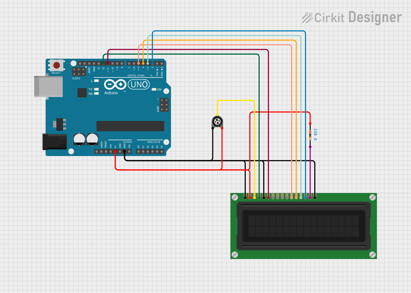
- Connect the VSS pin to ground and the VDD pin to a 5V power supply.
- Use a 10kΩ potentiometer to adjust the contrast by connecting its middle pin to V0.
- Connect the RS, RW, and E pins to digital output pins on your microcontroller.
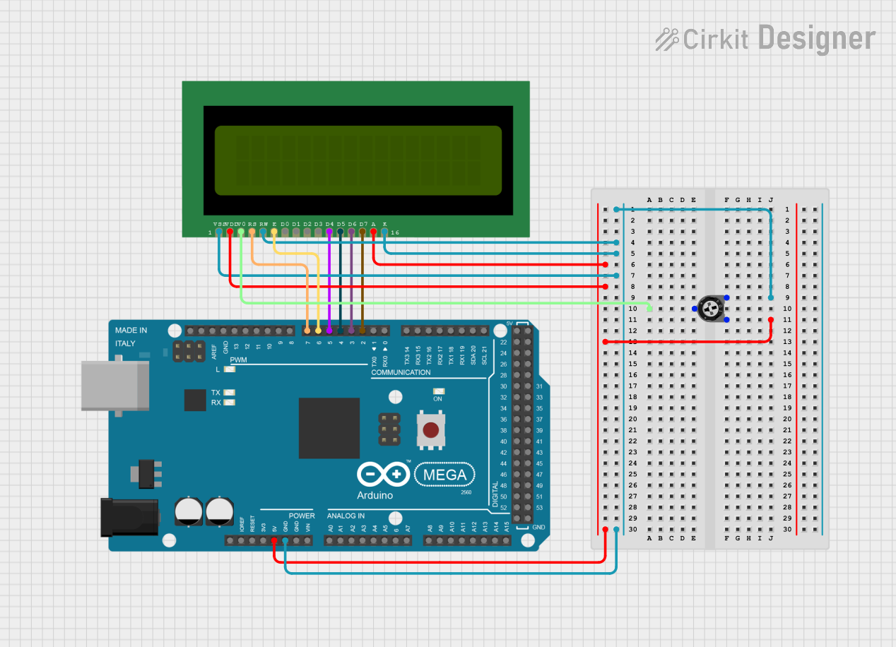
- For 4-bit mode, connect only D4-D7 to the microcontroller. For 8-bit mode, connect all data pins (D0-D7).
- Connect the LED+ pin to 5V through a 220Ω resistor and the LED- pin to ground for backlight functionality.
Example: Using the LCD with Arduino UNO
Below is an example of how to use the 16-pin LCD in 4-bit mode with an Arduino UNO:
#include <LiquidCrystal.h>

// Initialize the library with the pins connected to the LCD
// RS = pin 7, E = pin 8, D4-D7 = pins 9, 10, 11, 12
LiquidCrystal lcd(7, 8, 9, 10, 11, 12);

void setup() {
  lcd.begin(16, 2); // Set up the LCD's number of columns and rows
  lcd.print("Hello, World!"); // Print a message to the LCD
}

void loop() {
  lcd.setCursor(0, 1); // Move the cursor to the second row
  lcd.print(millis() / 1000); // Display the number of seconds since reset
}
Important Considerations
- Always use a current-limiting resistor (220Ω) for the backlight to prevent damage.
- Ensure proper grounding to avoid noise or flickering on the display.
- Use a potentiometer to fine-tune the contrast for optimal visibility.
- Avoid leaving the LCD in direct sunlight for extended periods, as it may degrade the display.
Troubleshooting and FAQs
Common Issues and Solutions
No display on the screen:
- Verify the power connections to VDD and VSS.
- Check the contrast adjustment on the V0 pin.
- Ensure the backlight pins (LED+ and LED-) are properly connected.
Flickering or garbled characters:
- Ensure proper grounding of the circuit.
- Check the timing of the enable pin (E) in your code.
- Verify that the data pins are securely connected.
Backlight not working:
- Confirm the resistor value for the backlight is appropriate (220Ω recommended).
- Check the polarity of the backlight connections (LED+ and LED-).
Characters not displaying correctly:
- Ensure the LCD is initialized in the correct mode (4-bit or 8-bit).
- Verify the wiring of the data pins (D4-D7 or D0-D7) to the microcontroller.
FAQs
Q: Can I use the LCD with a 3.3V microcontroller?
A: Yes, but you will need a level shifter or resistor divider to step down the 5V signals to 3.3V.
Q: How do I display custom characters?
A: Use the createChar() function in the LiquidCrystal library to define custom characters.
Q: Can I use the LCD without a backlight?
A: Yes, the LCD will still function without a backlight, but visibility may be reduced in low-light conditions.
Q: What is the maximum cable length for connecting the LCD?
A: Keep the cable length as short as possible (less than 30cm) to avoid signal degradation.
By following this documentation, you can effectively integrate the 16-pin LCD into your projects and troubleshoot common issues with ease.