How to Use CS-D808 stepper driver: Examples, Pinouts, and Specs
Introduction
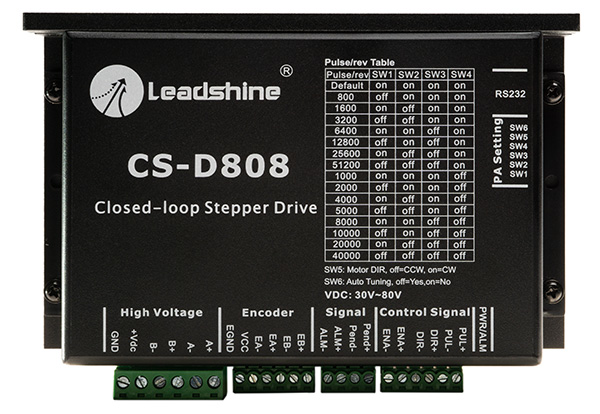
The CS-D808 Closed Loop Stepper Drive by Leadshine is a high-performance stepper motor driver designed for precise motion control. It is equipped with closed-loop control technology, ensuring accurate positioning and smooth operation. The driver supports microstepping, which enhances motion resolution and reduces vibration, making it ideal for applications requiring high precision and reliability.
Explore Projects Built with CS-D808 stepper driver
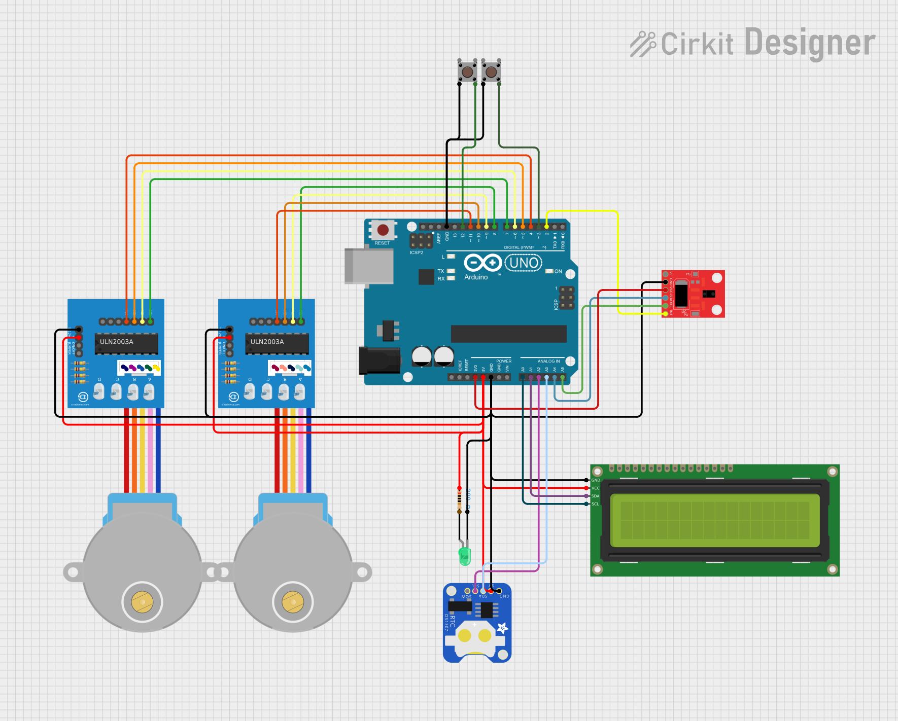


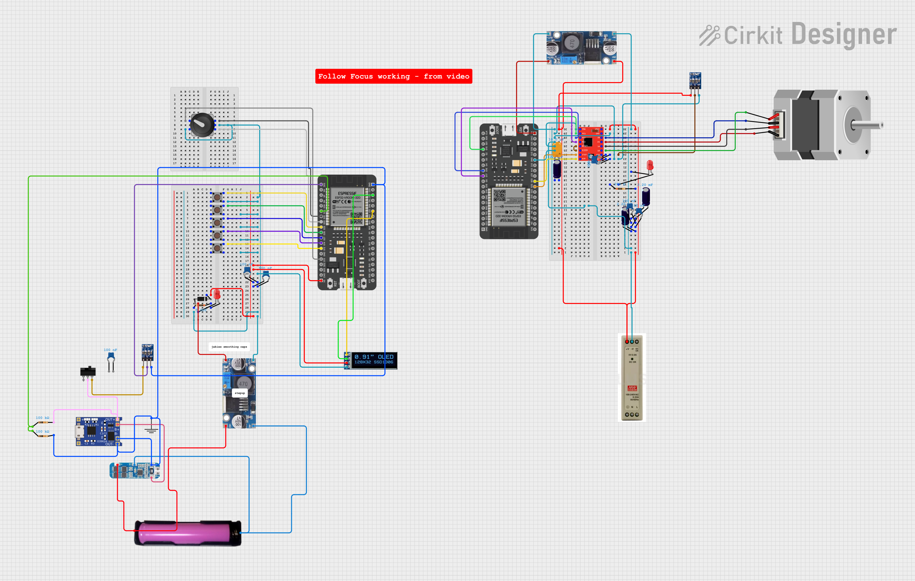
Explore Projects Built with CS-D808 stepper driver
Common Applications
- CNC machines
- Robotics and automation systems
- 3D printers
- Conveyor systems
- Medical equipment
- Laser cutters and engravers
Technical Specifications
Key Technical Details
| Parameter | Value |
|---|---|
| Manufacturer | Leadshine |
| Model | CS-D808 |
| Input Voltage Range | 24V to 80V DC |
| Output Current Range | 2.4A to 8.2A (peak) |
| Microstepping Resolution | Up to 51200 steps/rev |
| Control Signal Input | Pulse/Direction or CW/CCW |
| Feedback Type | Closed-loop with encoder feedback |
| Protection Features | Over-voltage, over-current, and overheat |
| Operating Temperature | 0°C to 50°C |
| Dimensions | 118 x 75.5 x 34 mm |
Pin Configuration and Descriptions
The CS-D808 features multiple connectors for power, motor, and control signal connections. Below is the pin configuration for the key connectors:
Control Signal Connector (P1)
| Pin Number | Name | Description |
|---|---|---|
| 1 | PUL+ | Pulse signal input (positive) |
| 2 | PUL- | Pulse signal input (negative) |
| 3 | DIR+ | Direction signal input (positive) |
| 4 | DIR- | Direction signal input (negative) |
| 5 | ENA+ | Enable signal input (positive) |
| 6 | ENA- | Enable signal input (negative) |
Power and Motor Connector
| Pin Number | Name | Description |
|---|---|---|
| 1 | V+ | Power supply positive (24V-80V DC) |
| 2 | V- | Power supply negative (GND) |
| 3 | A+ | Motor phase A positive |
| 4 | A- | Motor phase A negative |
| 5 | B+ | Motor phase B positive |
| 6 | B- | Motor phase B negative |
Encoder Feedback Connector
| Pin Number | Name | Description |
|---|---|---|
| 1 | EA+ | Encoder channel A positive |
| 2 | EA- | Encoder channel A negative |
| 3 | EB+ | Encoder channel B positive |
| 4 | EB- | Encoder channel B negative |
| 5 | VCC | Encoder power supply (5V) |
| 6 | GND | Encoder ground |
Usage Instructions
How to Use the CS-D808 in a Circuit
- Power Supply: Connect a DC power supply (24V-80V) to the V+ and V- terminals. Ensure the power supply can provide sufficient current for the motor.
- Motor Connection: Connect the stepper motor's phase wires to the A+, A-, B+, and B- terminals. Double-check the wiring to avoid damage.
- Control Signals: Connect the PUL, DIR, and ENA pins to a microcontroller or motion controller. Use optocouplers if necessary to isolate the control signals.
- Encoder Feedback: Connect the encoder wires to the EA+, EA-, EB+, EB-, VCC, and GND pins. Ensure proper polarity and secure connections.
- Microstepping Configuration: Set the DIP switches on the driver to configure the desired microstepping resolution and current limit.
- Testing: Power on the system and send pulse and direction signals to the driver. Verify motor movement and adjust settings as needed.
Important Considerations
- Power Supply: Use a regulated DC power supply within the specified voltage range.
- Heat Dissipation: Mount the driver on a heat sink or metal surface to ensure proper heat dissipation.
- Signal Integrity: Use shielded cables for control signals to minimize noise interference.
- Encoder Wiring: Ensure the encoder is properly aligned and securely connected to avoid feedback errors.
Arduino UNO Example Code
The following example demonstrates how to control the CS-D808 using an Arduino UNO:
// Define control signal pins
const int pulsePin = 2;  // Pulse signal connected to pin 2
const int dirPin = 3;    // Direction signal connected to pin 3
const int enaPin = 4;    // Enable signal connected to pin 4

void setup() {
  // Set pins as outputs
  pinMode(pulsePin, OUTPUT);
  pinMode(dirPin, OUTPUT);
  pinMode(enaPin, OUTPUT);

  // Enable the driver
  digitalWrite(enaPin, HIGH); // Set enable pin HIGH to activate the driver
}

void loop() {
  // Set direction
  digitalWrite(dirPin, HIGH); // Set direction to clockwise

  // Generate pulses for motor movement
  for (int i = 0; i < 200; i++) { // Move 200 steps
    digitalWrite(pulsePin, HIGH); // Pulse HIGH
    delayMicroseconds(500);       // 500 µs delay
    digitalWrite(pulsePin, LOW);  // Pulse LOW
    delayMicroseconds(500);       // 500 µs delay
  }

  delay(1000); // Wait for 1 second

  // Change direction
  digitalWrite(dirPin, LOW); // Set direction to counterclockwise

  // Generate pulses for motor movement
  for (int i = 0; i < 200; i++) { // Move 200 steps
    digitalWrite(pulsePin, HIGH); // Pulse HIGH
    delayMicroseconds(500);       // 500 µs delay
    digitalWrite(pulsePin, LOW);  // Pulse LOW
    delayMicroseconds(500);       // 500 µs delay
  }

  delay(1000); // Wait for 1 second
}
Troubleshooting and FAQs
Common Issues and Solutions
Motor Not Moving
- Cause: Incorrect wiring or loose connections.
- Solution: Double-check all connections, especially the motor and control signal wires.
Overheating
- Cause: Insufficient heat dissipation or excessive current setting.
- Solution: Mount the driver on a heat sink and reduce the current setting.
Erratic Motor Movement
- Cause: Noise interference or incorrect microstepping configuration.
- Solution: Use shielded cables for control signals and verify DIP switch settings.
Encoder Feedback Errors
- Cause: Misaligned or disconnected encoder.
- Solution: Ensure the encoder is properly aligned and securely connected.
FAQs
Q: Can the CS-D808 drive any stepper motor?
A: The CS-D808 is compatible with 2-phase stepper motors. Ensure the motor's voltage and current ratings match the driver's specifications.Q: How do I configure the microstepping resolution?
A: Use the DIP switches on the driver to set the desired microstepping resolution. Refer to the user manual for the DIP switch settings.Q: Is the driver compatible with 3.3V logic signals?
A: Yes, the CS-D808 supports both 3.3V and 5V logic signals for control inputs.Q: What happens if the encoder is disconnected?
A: The driver will detect a feedback error and stop the motor to prevent damage.
This concludes the documentation for the CS-D808 Closed Loop Stepper Drive. For further assistance, refer to the official Leadshine user manual or contact technical support.