
How to Use NODEMCU-32S : Examples, Pinouts, and Specs
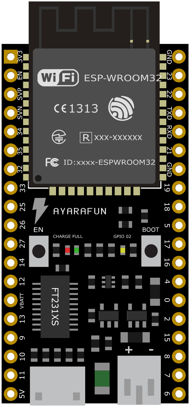
 Design with NODEMCU-32S in Cirkit Designer
Introduction
The NODEMCU-32S is a low-cost, open-source IoT platform built around the powerful ESP32 microcontroller. It is designed for wireless applications, featuring integrated Wi-Fi and Bluetooth capabilities. This board is ideal for developing connected projects, offering a versatile set of GPIO pins for interfacing with sensors, actuators, and other peripherals. Additionally, the NODEMCU-32S supports programming in the Arduino IDE, making it accessible to both beginners and experienced developers.
Explore Projects Built with NODEMCU-32S
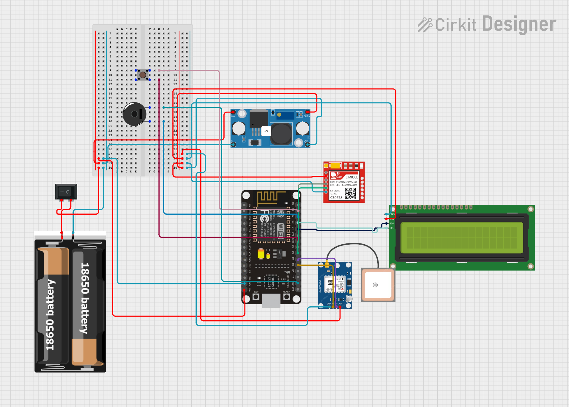 Open Project in Cirkit Designer
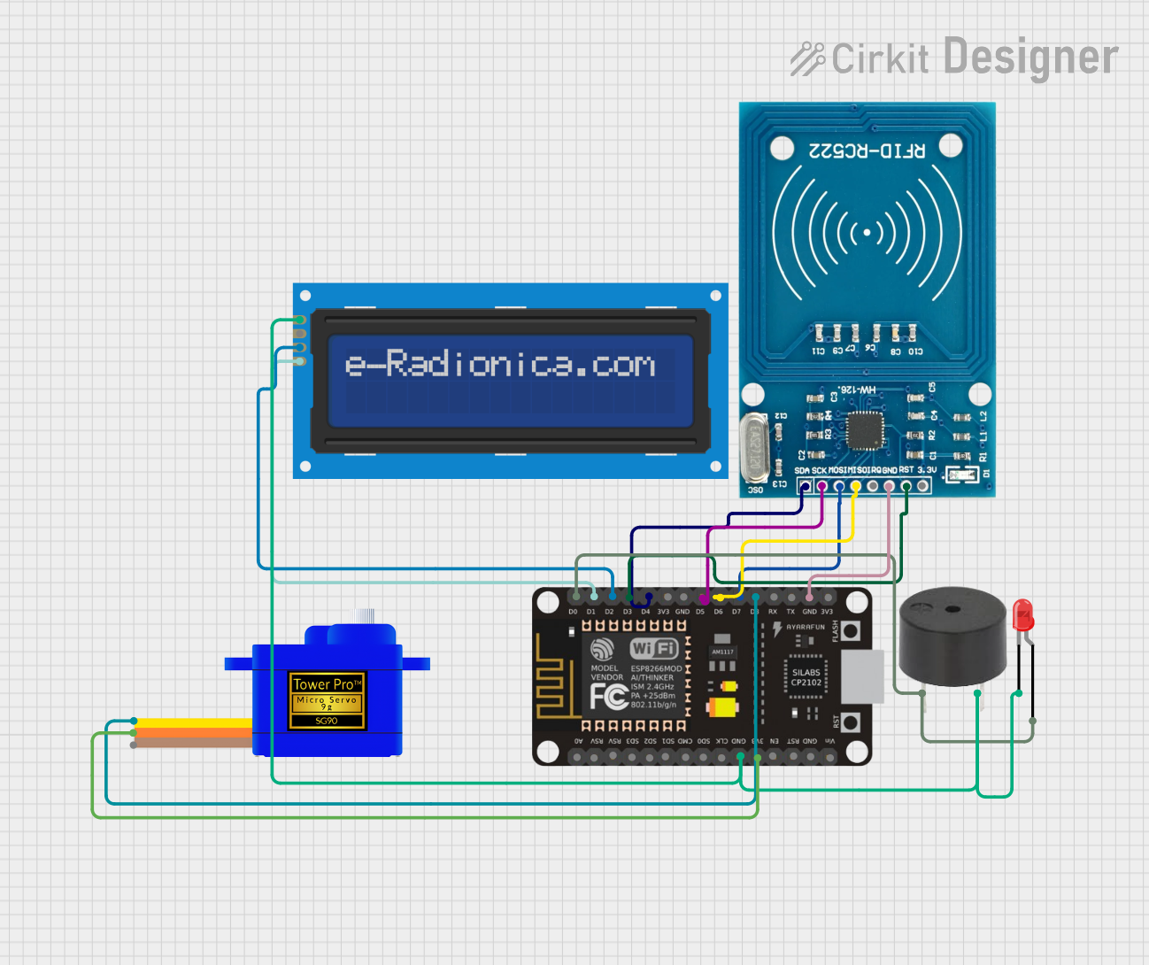 Open Project in Cirkit Designer
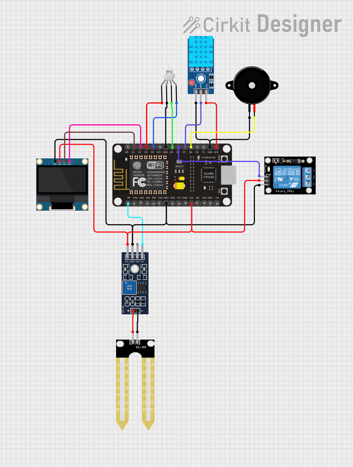 Open Project in Cirkit Designer
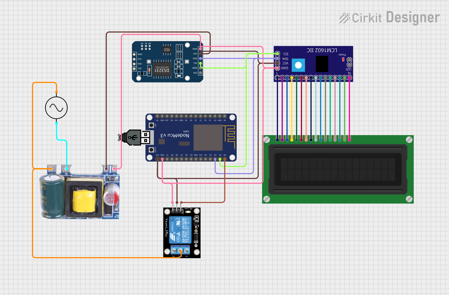 Open Project in Cirkit Designer
Explore Projects Built with NODEMCU-32S
Open Project in Cirkit DesignerOpen Project in Cirkit DesignerOpen Project in Cirkit DesignerOpen Project in Cirkit DesignerCommon Applications and Use Cases
- Home automation systems
- IoT devices and prototypes
- Wireless sensor networks
- Smart appliances
- Remote monitoring and control systems
- Wearable devices
Technical Specifications
The NODEMCU-32S is equipped with robust hardware features that make it suitable for a wide range of applications. Below are its key technical specifications:
| Specification | Details |
|---|---|
| Microcontroller | ESP32 (dual-core Xtensa LX6 processor) |
| Clock Speed | Up to 240 MHz |
| Flash Memory | 4 MB |
| SRAM | 520 KB |
| Wi-Fi | 802.11 b/g/n |
| Bluetooth | Bluetooth 4.2 (Classic and BLE) |
| Operating Voltage | 3.3V |
| Input Voltage (VIN) | 5V (via USB or external power supply) |
| GPIO Pins | 30 (including ADC, DAC, PWM, I2C, SPI, UART) |
| ADC Resolution | 12-bit |
| DAC Resolution | 8-bit |
| USB Interface | Micro-USB |
| Dimensions | 58 mm x 31 mm |
Pin Configuration and Descriptions
The NODEMCU-32S has a total of 30 GPIO pins, each with specific functions. Below is a summary of the pin configuration:
| Pin | Function | Description |
|---|---|---|
| VIN | Power Input | Accepts 5V input for powering the board. |
| GND | Ground | Common ground for the circuit. |
| 3V3 | Power Output | Provides 3.3V output for external components. |
| GPIO0 | General Purpose I/O, Boot Mode | Used for boot mode selection during programming. |
| GPIO1 | UART TX | Transmit pin for UART communication. |
| GPIO3 | UART RX | Receive pin for UART communication. |
| GPIO12 | ADC, PWM, GPIO | Analog input, PWM output, or general-purpose I/O. |
| GPIO13 | ADC, PWM, GPIO | Analog input, PWM output, or general-purpose I/O. |
| GPIO14 | ADC, PWM, GPIO | Analog input, PWM output, or general-purpose I/O. |
| GPIO15 | ADC, PWM, GPIO | Analog input, PWM output, or general-purpose I/O. |
| GPIO16 | GPIO | General-purpose I/O. |
| GPIO17 | GPIO | General-purpose I/O. |
| EN | Enable | Enables or disables the board. |
| RST | Reset | Resets the microcontroller. |
Usage Instructions
How to Use the NODEMCU-32S in a Circuit
Powering the Board:
- Connect the NODEMCU-32S to your computer via a Micro-USB cable for power and programming.
- Alternatively, supply 5V to the VIN pin and connect GND to the ground of your power source.
Programming the Board:
- Install the Arduino IDE and add the ESP32 board support package.
- Select "NodeMCU-32S" as the board in the Arduino IDE.
- Write your code and upload it to the board using the Micro-USB connection.
Connecting Peripherals:
- Use the GPIO pins to connect sensors, actuators, or other devices.
- Ensure that the voltage levels of connected devices are compatible with the 3.3V logic of the NODEMCU-32S.
Using Wi-Fi and Bluetooth:
- Leverage the built-in Wi-Fi and Bluetooth capabilities for wireless communication.
- Use libraries like
WiFi.horBluetoothSerial.hin the Arduino IDE to simplify development.
Important Considerations and Best Practices
- Voltage Levels: The GPIO pins operate at 3.3V. Avoid connecting 5V devices directly to the pins without a level shifter.
- Power Supply: Ensure a stable power supply to avoid unexpected resets or malfunctions.
- Boot Mode: To enter bootloader mode for programming, hold down the "BOOT" button while pressing the "EN" (reset) button.
- Heat Management: The ESP32 can get warm during operation. Ensure proper ventilation if used in enclosed spaces.
Example Code for Arduino IDE
Below is an example of how to connect the NODEMCU-32S to a Wi-Fi network and blink an LED:
#include <WiFi.h> // Include the Wi-Fi library

const char* ssid = "Your_SSID";       // Replace with your Wi-Fi network name
const char* password = "Your_Password"; // Replace with your Wi-Fi password
const int ledPin = 2;                 // GPIO2 is typically connected to the onboard LED

void setup() {
  pinMode(ledPin, OUTPUT);            // Set the LED pin as an output
  Serial.begin(115200);               // Start the serial communication
  Serial.println("Connecting to Wi-Fi...");

  WiFi.begin(ssid, password);         // Connect to the Wi-Fi network
  while (WiFi.status() != WL_CONNECTED) {
    delay(1000);                      // Wait for the connection to establish
    Serial.println("Connecting...");
  }

  Serial.println("Connected to Wi-Fi!");
  Serial.print("IP Address: ");
  Serial.println(WiFi.localIP());     // Print the device's IP address
}

void loop() {
  digitalWrite(ledPin, HIGH);         // Turn the LED on
  delay(1000);                        // Wait for 1 second
  digitalWrite(ledPin, LOW);          // Turn the LED off
  delay(1000);                        // Wait for 1 second
}
Troubleshooting and FAQs
Common Issues and Solutions
The board is not detected by the Arduino IDE:
- Ensure the correct USB driver is installed for the NODEMCU-32S.
- Check that the correct COM port is selected in the Arduino IDE.
Wi-Fi connection fails:
- Double-check the SSID and password in your code.
- Ensure the Wi-Fi network is within range and operational.
GPIO pins not working as expected:
- Verify that the pins are not being used for other functions (e.g., boot mode).
- Check for proper connections and ensure the voltage levels are correct.
Frequent resets or instability:
- Use a stable power supply with sufficient current (at least 500mA).
- Avoid excessive power draw from the GPIO pins.
FAQs
Q: Can I use the NODEMCU-32S with 5V sensors?
A: The GPIO pins operate at 3.3V. Use a level shifter to safely interface with 5V sensors.
Q: How do I reset the board?
A: Press the "EN" button to reset the microcontroller.
Q: Can I use the NODEMCU-32S for battery-powered projects?
A: Yes, you can power the board using a 3.7V LiPo battery with a suitable voltage regulator.
Q: Is the NODEMCU-32S compatible with ESP-IDF?
A: Yes, the NODEMCU-32S can be programmed using the ESP-IDF framework for advanced development.