How to Use CB Connector 8 pin (male): Examples, Pinouts, and Specs
Introduction
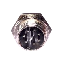
The CB Connector 8 Pin (Male) is a versatile electrical connector designed to establish reliable connections in electronic devices. With its 8-pin configuration, it is commonly used in communication and control systems, as well as in industrial and consumer electronics. This connector ensures secure and efficient signal or power transmission between components.
Explore Projects Built with CB Connector 8 pin (male)


Explore Projects Built with CB Connector 8 pin (male)
Common Applications and Use Cases
- Communication systems (e.g., radios, intercoms)
- Control systems in industrial automation
- Consumer electronics (e.g., audio equipment, gaming devices)
- Robotics and embedded systems
- Prototyping and development boards
Technical Specifications
Below are the key technical details and pin configuration for the CB Connector 8 Pin (Male):
Key Technical Details
| Parameter | Specification |
|---|---|
| Manufacturer | [Insert Manufacturer Name] |
| Manufacturer Part ID | [Insert Manufacturer Part ID] |
| Number of Pins | 8 |
| Connector Type | Male |
| Contact Material | Copper alloy (plated) |
| Insulation Material | Thermoplastic |
| Voltage Rating | 250V AC/DC |
| Current Rating | 3A per pin |
| Operating Temperature | -40°C to +85°C |
| Mounting Style | Panel mount or cable mount |
| Durability | 500 mating cycles |
Pin Configuration and Descriptions
The CB Connector 8 Pin (Male) features 8 pins, each of which can be assigned specific functions depending on the application. Below is a general pinout table:
| Pin Number | Description | Typical Use Case |
|---|---|---|
| 1 | Ground (GND) | Common ground connection |
| 2 | Power Supply (VCC) | Positive voltage input |
| 3 | Data Line 1 (D1) | Signal transmission or control |
| 4 | Data Line 2 (D2) | Signal transmission or control |
| 5 | Data Line 3 (D3) | Signal transmission or control |
| 6 | Data Line 4 (D4) | Signal transmission or control |
| 7 | Reserved/Custom Function | User-defined purpose |
| 8 | Reserved/Custom Function | User-defined purpose |
Note: Pin assignments may vary depending on the specific application or circuit design. Always refer to the manufacturer's datasheet for precise details.
Usage Instructions
How to Use the CB Connector 8 Pin (Male) in a Circuit
- Identify Pin Functions: Refer to the pin configuration table to understand the purpose of each pin.
- Soldering or Crimping: If the connector is cable-mounted, solder or crimp the wires to the corresponding pins. For panel-mounted connectors, ensure proper alignment and secure mounting.
- Mating with Female Connector: Align the male connector with the corresponding female connector and gently push until it clicks or locks into place.
- Verify Connections: Use a multimeter to check continuity and ensure proper connections before powering the circuit.
Important Considerations and Best Practices
- Avoid Overloading: Do not exceed the voltage and current ratings to prevent damage to the connector or circuit.
- Secure Mounting: Ensure the connector is firmly mounted to avoid accidental disconnections.
- Environmental Protection: If used in harsh environments, consider using a connector with an IP-rated housing for protection against dust and moisture.
- Polarity Check: Double-check the polarity of power and ground connections to avoid short circuits.
- Cable Strain Relief: Use strain relief mechanisms to prevent stress on the wires and pins.
Example: Connecting to an Arduino UNO
The CB Connector 8 Pin (Male) can be used to interface external devices with an Arduino UNO. Below is an example of connecting a sensor using this connector:
Circuit Diagram
- Pin 1 (GND) → Arduino GND
- Pin 2 (VCC) → Arduino 5V
- Pin 3 (D1) → Arduino Digital Pin 2
- Pin 4 (D2) → Arduino Digital Pin 3
Arduino Code
// Example code for reading data from a sensor connected via CB Connector 8 Pin

const int sensorPin1 = 2; // Pin 3 of the connector is connected to Digital Pin 2
const int sensorPin2 = 3; // Pin 4 of the connector is connected to Digital Pin 3

void setup() {
  pinMode(sensorPin1, INPUT); // Set sensorPin1 as input
  pinMode(sensorPin2, INPUT); // Set sensorPin2 as input
  Serial.begin(9600);         // Initialize serial communication
}

void loop() {
  int sensorValue1 = digitalRead(sensorPin1); // Read data from sensorPin1
  int sensorValue2 = digitalRead(sensorPin2); // Read data from sensorPin2

  // Print the sensor values to the Serial Monitor
  Serial.print("Sensor 1 Value: ");
  Serial.println(sensorValue1);
  Serial.print("Sensor 2 Value: ");
  Serial.println(sensorValue2);

  delay(1000); // Wait for 1 second before reading again
}
Note: Modify the code and pin assignments based on your specific application.
Troubleshooting and FAQs
Common Issues and Solutions
| Issue | Possible Cause | Solution |
|---|---|---|
| No connection or intermittent signal | Loose or improper mating of connectors | Ensure connectors are securely mated |
| Overheating of connector | Exceeding current or voltage ratings | Reduce load to within rated limits |
| Signal noise or interference | Poor grounding or shielding | Improve grounding and use shielded cables |
| Broken or bent pins | Excessive force during mating | Handle connectors gently and inspect pins |
FAQs
Can this connector handle high-frequency signals?
Yes, but ensure proper shielding and grounding to minimize interference.Is this connector waterproof?
The standard version is not waterproof. Use an IP-rated version for outdoor or harsh environments.Can I use this connector for power transmission?
Yes, as long as the current and voltage do not exceed the specified ratings.What tools are required for installation?
Depending on the type, you may need a soldering iron, crimping tool, or screwdriver.
By following this documentation, you can effectively integrate the CB Connector 8 Pin (Male) into your projects and ensure reliable performance.