How to Use HC12: Examples, Pinouts, and Specs
Introduction
The HC12 is a low-cost, low-power wireless transceiver module that operates in the 433MHz frequency band. It is designed for long-range communication and supports a simple serial communication interface, making it easy to integrate into various projects. The module is capable of transmitting data over distances of up to 1,000 meters in open space, making it ideal for applications requiring reliable wireless communication.
Explore Projects Built with HC12
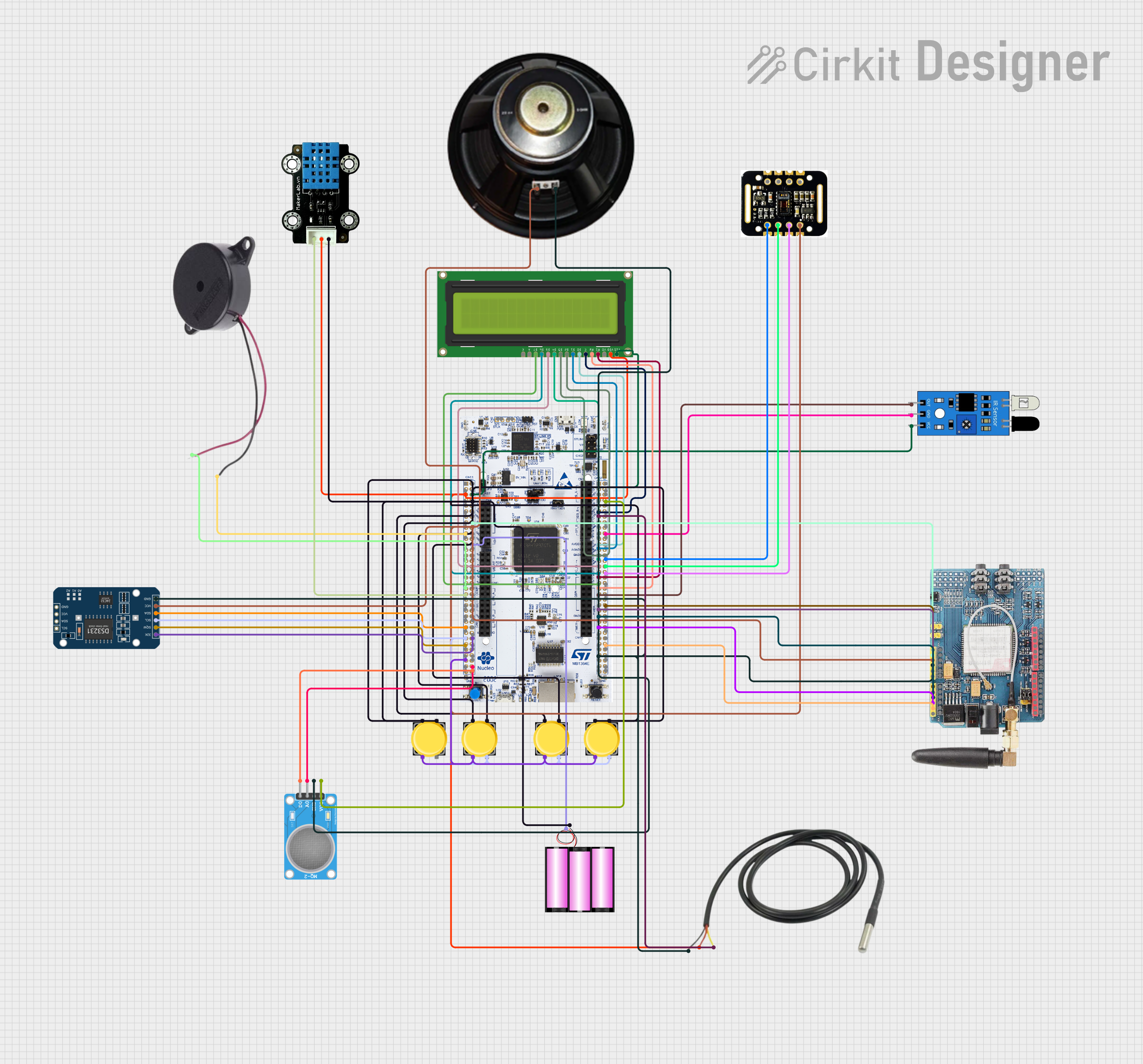


Explore Projects Built with HC12
Common Applications and Use Cases
- Remote control systems
- Wireless sensor networks
- Home automation
- Industrial monitoring and control
- Robotics and UAV communication
- IoT (Internet of Things) devices
Technical Specifications
The HC12 module is equipped with a powerful wireless transceiver and a built-in microcontroller for handling communication protocols. Below are the key technical details:
| Parameter | Specification |
|---|---|
| Operating Frequency | 433.4 MHz to 473.0 MHz |
| Communication Range | Up to 1,000 meters (open space) |
| Modulation Method | GFSK (Gaussian Frequency Shift Keying) |
| Supply Voltage | 3.2V to 5.5V |
| Operating Current | 16 mA (transmitting), 3.5 mA (idle) |
| Baud Rate | 1,200 to 115,200 bps (configurable) |
| Transmit Power | Up to 100 mW (20 dBm) |
| Antenna Interface | SMA or spring antenna |
| Operating Temperature | -40°C to +85°C |
Pin Configuration and Descriptions
The HC12 module has a 4-pin interface for easy integration with microcontrollers. Below is the pinout:
| Pin | Name | Description |
|---|---|---|
| 1 | VCC | Power supply input (3.2V to 5.5V). Connect to the 3.3V or 5V pin of your MCU. |
| 2 | GND | Ground. Connect to the ground of your circuit. |
| 3 | TXD | Transmit data. Connect to the RX pin of your microcontroller. |
| 4 | RXD | Receive data. Connect to the TX pin of your microcontroller. |
| 5 | SET | Configuration mode pin. Pull LOW to enter setup mode, HIGH for normal operation. |
Usage Instructions
The HC12 module is straightforward to use and can be connected to a microcontroller, such as an Arduino UNO, via its serial interface. Below are the steps to use the HC12 in a circuit:
Basic Circuit Connection
- Power the Module: Connect the VCC pin to a 3.3V or 5V power source and the GND pin to the ground.
- Connect Serial Pins:
- Connect the TXD pin of the HC12 to the RX pin of the microcontroller.
- Connect the RXD pin of the HC12 to the TX pin of the microcontroller.
- SET Pin Configuration:
- Pull the SET pin HIGH (or leave it unconnected) for normal operation.
- Pull the SET pin LOW to enter configuration mode for changing parameters like baud rate or channel.
Example Arduino Code
Below is an example of how to use the HC12 module with an Arduino UNO for basic communication:
#include <SoftwareSerial.h>

// Define HC12 RX and TX pins
SoftwareSerial HC12(10, 11); // RX = Pin 10, TX = Pin 11

void setup() {
  Serial.begin(9600);       // Start serial communication with PC
  HC12.begin(9600);         // Start serial communication with HC12
  Serial.println("HC12 Test Program");
}

void loop() {
  // Check if data is received from the HC12 module
  if (HC12.available()) {
    String receivedData = HC12.readString(); // Read data from HC12
    Serial.print("Received: ");
    Serial.println(receivedData);           // Print received data to Serial Monitor
  }

  // Check if data is sent from the Serial Monitor
  if (Serial.available()) {
    String sendData = Serial.readString();  // Read data from Serial Monitor
    HC12.print(sendData);                   // Send data to HC12
  }
}
Important Considerations and Best Practices
- Antenna Selection: Use a proper antenna (SMA or spring) to maximize the communication range.
- Power Supply: Ensure a stable power supply to avoid communication issues.
- Baud Rate Matching: The baud rate of the HC12 must match the baud rate of the microcontroller.
- Interference: Avoid placing the module near sources of electromagnetic interference (e.g., motors, high-frequency circuits).
Troubleshooting and FAQs
Common Issues and Solutions
No Communication Between Modules:
- Ensure both modules are set to the same channel and baud rate.
- Verify the TX and RX connections between the HC12 and the microcontroller.
Short Communication Range:
- Check the antenna connection and ensure it is properly installed.
- Avoid obstructions and interference in the communication path.
Module Not Responding in Configuration Mode:
- Ensure the SET pin is pulled LOW during power-up to enter configuration mode.
- Verify the serial connection and baud rate (default is 9,600 bps).
Data Corruption or Loss:
- Use a lower baud rate for long-distance communication to improve reliability.
- Ensure a stable power supply and proper grounding.
FAQs
Q: Can the HC12 communicate with other 433MHz devices?
A: No, the HC12 uses a proprietary protocol and cannot directly communicate with other 433MHz devices unless they use the same protocol.
Q: How do I change the HC12's baud rate or channel?
A: Enter configuration mode by pulling the SET pin LOW, then send AT commands via the serial interface. For example, use AT+B9600 to set the baud rate to 9,600 bps.
Q: Can I use multiple HC12 modules in the same area?
A: Yes, you can use multiple modules by assigning them different channels to avoid interference.
Q: What is the maximum data rate supported by the HC12?
A: The HC12 supports a maximum baud rate of 115,200 bps, but lower rates are recommended for long-range communication.
By following this documentation, you can effectively integrate the HC12 module into your projects and troubleshoot common issues.