Cirkit Designer Logo
Cirkit Designer
Your all-in-one circuit design IDE
Home / 
Component Documentation

How to Use XIAO RS485 Breakout Board: Examples, Pinouts, and Specs

Image of XIAO RS485 Breakout Board
Cirkit Designer LogoDesign with XIAO RS485 Breakout Board in Cirkit Designer

Introduction

The XIAO RS485 Breakout Board by SEEED Studio is a compact and versatile module designed for robust RS485 communication. It integrates a XIAO microcontroller, making it an ideal solution for projects requiring reliable serial communication over long distances. RS485 is widely used in industrial automation, building management systems, and other applications where noise-resistant, long-distance communication is essential.

Explore Projects Built with XIAO RS485 Breakout Board

Use Cirkit Designer to design, explore, and prototype these projects online. Some projects support real-time simulation. Click "Open Project" to start designing instantly!
ESP8266 NodeMCU with LoRa and RS-485 Communication Interface
Image of RS485 Serial USB: A project utilizing XIAO RS485 Breakout Board in a practical application
This circuit features two ESP8266 NodeMCU microcontrollers, each interfaced with a LoRa Ra-02 SX1278 module for long-range wireless communication, and an RS-485 module for wired serial communication. The ESP8266 microcontrollers are responsible for handling the communication protocols and data processing. Power is supplied to the microcontrollers via an MB102 Breadboard Power Supply Module, which provides both 3.3V and 5V outputs.
Cirkit Designer LogoOpen Project in Cirkit Designer
ESP8266 NodeMCU with LoRa and RS-485 Communication and Ethernet Connectivity
Image of Wiring Diagram LoRa: A project utilizing XIAO RS485 Breakout Board in a practical application
This circuit serves as a multi-protocol communication hub featuring two ESP8266 NodeMCUs for processing, each connected to a LoRa Ra-02 SX1278 for long-range wireless communication. One NodeMCU is also connected to an RS-485 module for serial communication and a W5500 Ethernet module for network connectivity, with MB102 modules supplying power.
Cirkit Designer LogoOpen Project in Cirkit Designer
ESP32-Based Industrial Control System with RS485 Communication and I2C Interface
Image of DRIVER TESTER : A project utilizing XIAO RS485 Breakout Board in a practical application
This circuit integrates a microcontroller with a display, digital potentiometer, IO expander, and opto-isolator board for signal interfacing and isolation. It includes a UART to RS485 converter for serial communication and a power converter to step down voltage for the system. The circuit is designed for control and communication in an isolated and protected environment.
Cirkit Designer LogoOpen Project in Cirkit Designer
STM32 and Arduino UNO Based Dual RS485 Communication Interface
Image of STM to Arduino RS485: A project utilizing XIAO RS485 Breakout Board in a practical application
This circuit consists of two microcontrollers, an STM32F103C8T6 and an Arduino UNO, each interfaced with separate RS485 transceiver modules for serial communication. The STM32F103C8T6 controls the RE (Receiver Enable) and DE (Driver Enable) pins of one RS485 module to manage its operation, and communicates via the A9 and A10 pins for DI (Data Input) and RO (Receiver Output), respectively. The Arduino UNO is similarly connected to another RS485 module, with digital pins D2 and D3 interfacing with DI and RO, and D8 controlling both RE and DE. The RS485 modules are connected to each other through their A and B differential communication lines, enabling serial data exchange between the two microcontrollers over a robust and long-distance capable RS485 network.
Cirkit Designer LogoOpen Project in Cirkit Designer

Explore Projects Built with XIAO RS485 Breakout Board

Use Cirkit Designer to design, explore, and prototype these projects online. Some projects support real-time simulation. Click "Open Project" to start designing instantly!
Image of RS485 Serial USB: A project utilizing XIAO RS485 Breakout Board in a practical application
ESP8266 NodeMCU with LoRa and RS-485 Communication Interface
This circuit features two ESP8266 NodeMCU microcontrollers, each interfaced with a LoRa Ra-02 SX1278 module for long-range wireless communication, and an RS-485 module for wired serial communication. The ESP8266 microcontrollers are responsible for handling the communication protocols and data processing. Power is supplied to the microcontrollers via an MB102 Breadboard Power Supply Module, which provides both 3.3V and 5V outputs.
Cirkit Designer LogoOpen Project in Cirkit Designer
Image of Wiring Diagram LoRa: A project utilizing XIAO RS485 Breakout Board in a practical application
ESP8266 NodeMCU with LoRa and RS-485 Communication and Ethernet Connectivity
This circuit serves as a multi-protocol communication hub featuring two ESP8266 NodeMCUs for processing, each connected to a LoRa Ra-02 SX1278 for long-range wireless communication. One NodeMCU is also connected to an RS-485 module for serial communication and a W5500 Ethernet module for network connectivity, with MB102 modules supplying power.
Cirkit Designer LogoOpen Project in Cirkit Designer
Image of DRIVER TESTER : A project utilizing XIAO RS485 Breakout Board in a practical application
ESP32-Based Industrial Control System with RS485 Communication and I2C Interface
This circuit integrates a microcontroller with a display, digital potentiometer, IO expander, and opto-isolator board for signal interfacing and isolation. It includes a UART to RS485 converter for serial communication and a power converter to step down voltage for the system. The circuit is designed for control and communication in an isolated and protected environment.
Cirkit Designer LogoOpen Project in Cirkit Designer
Image of STM to Arduino RS485: A project utilizing XIAO RS485 Breakout Board in a practical application
STM32 and Arduino UNO Based Dual RS485 Communication Interface
This circuit consists of two microcontrollers, an STM32F103C8T6 and an Arduino UNO, each interfaced with separate RS485 transceiver modules for serial communication. The STM32F103C8T6 controls the RE (Receiver Enable) and DE (Driver Enable) pins of one RS485 module to manage its operation, and communicates via the A9 and A10 pins for DI (Data Input) and RO (Receiver Output), respectively. The Arduino UNO is similarly connected to another RS485 module, with digital pins D2 and D3 interfacing with DI and RO, and D8 controlling both RE and DE. The RS485 modules are connected to each other through their A and B differential communication lines, enabling serial data exchange between the two microcontrollers over a robust and long-distance capable RS485 network.
Cirkit Designer LogoOpen Project in Cirkit Designer

Common Applications and Use Cases

  • Industrial automation and control systems
  • Building management systems (e.g., HVAC, lighting control)
  • Long-distance serial communication
  • Data acquisition systems
  • IoT devices requiring RS485 connectivity

Technical Specifications

Below are the key technical details of the XIAO RS485 Breakout Board:

Specification Details
Microcontroller XIAO series microcontroller
Communication Protocol RS485 (half-duplex)
Operating Voltage 3.3V or 5V (selectable via jumper)
Power Supply Input 5V via USB-C or external power supply
Baud Rate Up to 1 Mbps
Operating Temperature -40°C to 85°C
Dimensions 23.5mm x 17.5mm x 3.5mm
Connector Type Terminal block for RS485, USB-C for power and programming
Protection Features Built-in ESD protection and short-circuit protection for RS485 lines

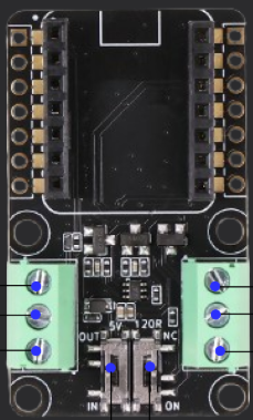
Pin Configuration and Descriptions

The XIAO RS485 Breakout Board features the following pinout:

RS485 Terminal Block

Pin Label Description
1 A RS485 Data Line A (non-inverting)
2 B RS485 Data Line B (inverting)
3 GND Ground connection for RS485 communication

Microcontroller Pins

Pin Label Description
1 TX UART Transmit Pin (connected to RS485 driver)
2 RX UART Receive Pin (connected to RS485 receiver)
3 VCC Power input (3.3V or 5V, selectable via jumper)
4 GND Ground connection

Usage Instructions

How to Use the Component in a Circuit

  1. Power the Board: Connect a 5V power supply via the USB-C port or an external power source. Ensure the jumper is set to the correct voltage (3.3V or 5V) for your application.
  2. Connect RS485 Lines: Use the terminal block to connect the RS485 A and B lines to your RS485 network. Ensure proper polarity (A to A, B to B).
  3. Connect to a Host Device: Use the USB-C port to program the XIAO microcontroller or communicate with a host device.
  4. Configure Communication: Set the desired baud rate and communication parameters in your microcontroller code.

Important Considerations and Best Practices

  • Termination Resistor: If the XIAO RS485 Breakout Board is at the end of the RS485 bus, ensure a 120-ohm termination resistor is connected across the A and B lines.
  • Grounding: Connect the GND pin of the breakout board to the ground of the RS485 network to ensure proper signal integrity.
  • Voltage Selection: Use the onboard jumper to select the appropriate operating voltage (3.3V or 5V) based on your system requirements.
  • ESD Protection: The board includes built-in ESD protection, but additional external protection may be required in high-noise environments.

Example Code for Arduino UNO

Below is an example of how to use the XIAO RS485 Breakout Board with an Arduino UNO for basic communication:

#include <SoftwareSerial.h>

// Define RS485 pins for SoftwareSerial
#define RS485_TX 10  // Pin 10 for TX
#define RS485_RX 11  // Pin 11 for RX
#define RS485_DE 9   // Pin 9 for Driver Enable

SoftwareSerial RS485Serial(RS485_RX, RS485_TX);

void setup() {
  pinMode(RS485_DE, OUTPUT); // Set DE pin as output
  digitalWrite(RS485_DE, LOW); // Set DE to LOW (receiver mode)
  
  RS485Serial.begin(9600); // Initialize RS485 communication at 9600 baud
  Serial.begin(9600);      // Initialize Serial Monitor
}

void loop() {
  // Send data over RS485
  digitalWrite(RS485_DE, HIGH); // Enable driver mode
  RS485Serial.println("Hello RS485!"); // Send message
  digitalWrite(RS485_DE, LOW);  // Enable receiver mode
  
  delay(1000); // Wait for 1 second
  
  // Receive data over RS485
  if (RS485Serial.available()) {
    String receivedData = RS485Serial.readString();
    Serial.println("Received: " + receivedData); // Print received data to Serial Monitor
  }
}

Notes on the Code

  • The RS485_DE pin is used to toggle between driver (transmit) and receiver modes.
  • Ensure the baud rate matches the settings of other devices on the RS485 network.
  • Use a logic level shifter if connecting the breakout board to a 5V microcontroller.

Troubleshooting and FAQs

Common Issues and Solutions

  1. No Communication on RS485 Bus

    • Verify the A and B lines are correctly connected to the RS485 network.
    • Check the termination resistor at the end of the RS485 bus.
    • Ensure the baud rate and communication parameters match across all devices.
  2. Data Corruption or Noise

    • Ensure proper grounding between all devices on the RS485 network.
    • Use shielded twisted-pair cables for long-distance communication.
    • Verify the operating voltage (3.3V or 5V) is correctly set using the jumper.
  3. Microcontroller Not Responding

    • Check the USB-C connection and ensure the board is powered.
    • Verify the microcontroller firmware is correctly uploaded.

FAQs

Q: Can I use the XIAO RS485 Breakout Board with a 5V microcontroller?
A: Yes, the board supports both 3.3V and 5V operation. Use the onboard jumper to select the appropriate voltage.

Q: What is the maximum communication distance for RS485?
A: RS485 supports communication distances of up to 1200 meters, depending on the baud rate and cable quality.

Q: Does the board support full-duplex communication?
A: No, the XIAO RS485 Breakout Board supports half-duplex communication only.

Q: Can I use this board with other microcontrollers besides XIAO?
A: Yes, the board can be used with any microcontroller that supports UART communication.