How to Use Flora 3-Pin JST: Examples, Pinouts, and Specs
Introduction
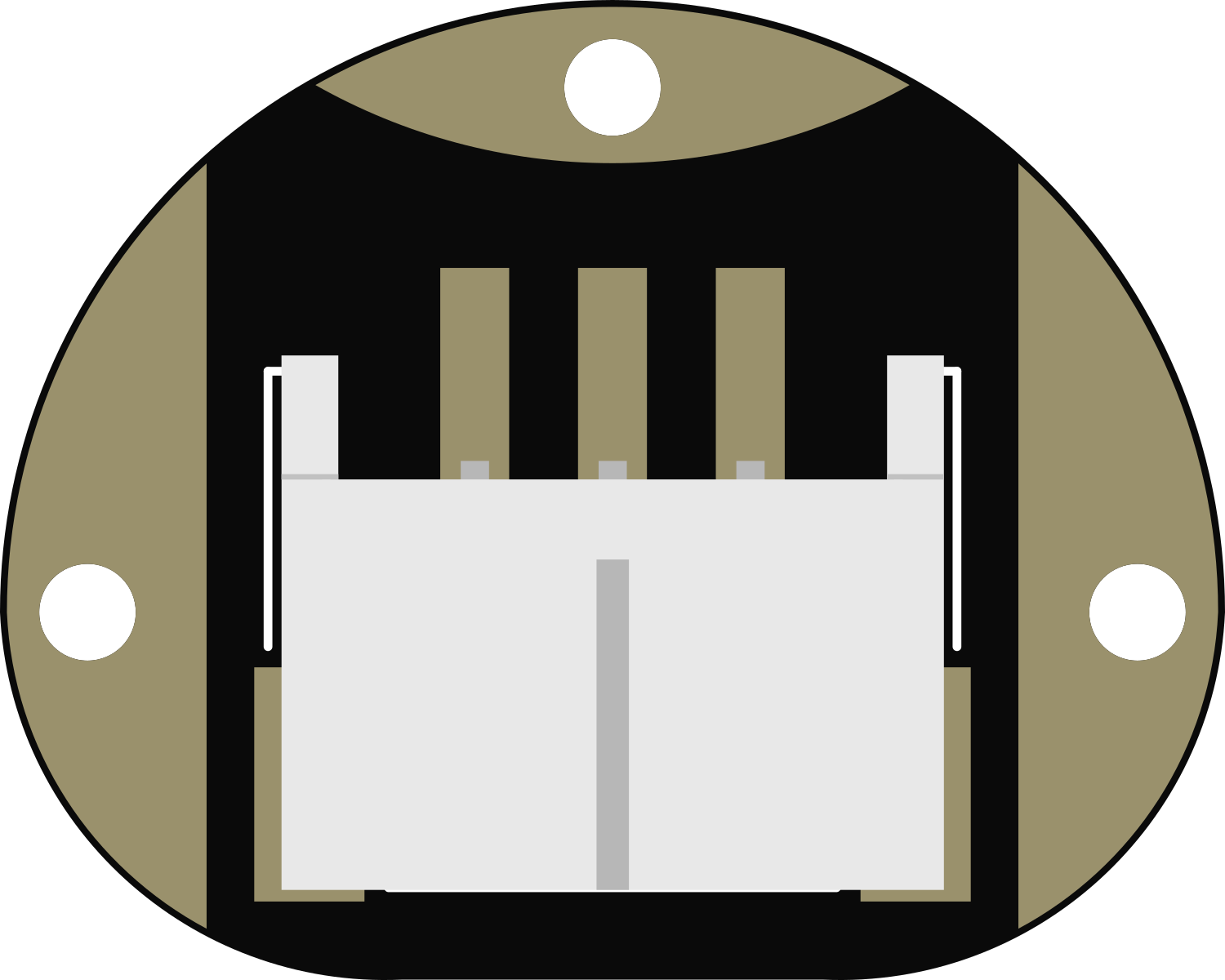
The Flora 3-Pin JST connector is a compact, reliable connector compatible with the Adafruit Flora board and other microcontroller platforms. It is designed to facilitate easy and secure connections between the Flora board and various peripherals such as sensors, LEDs, and other electronic components. The connector's design ensures a stable connection while allowing for quick disconnection when needed, making it ideal for wearable electronics and projects that require modularity.
Explore Projects Built with Flora 3-Pin JST
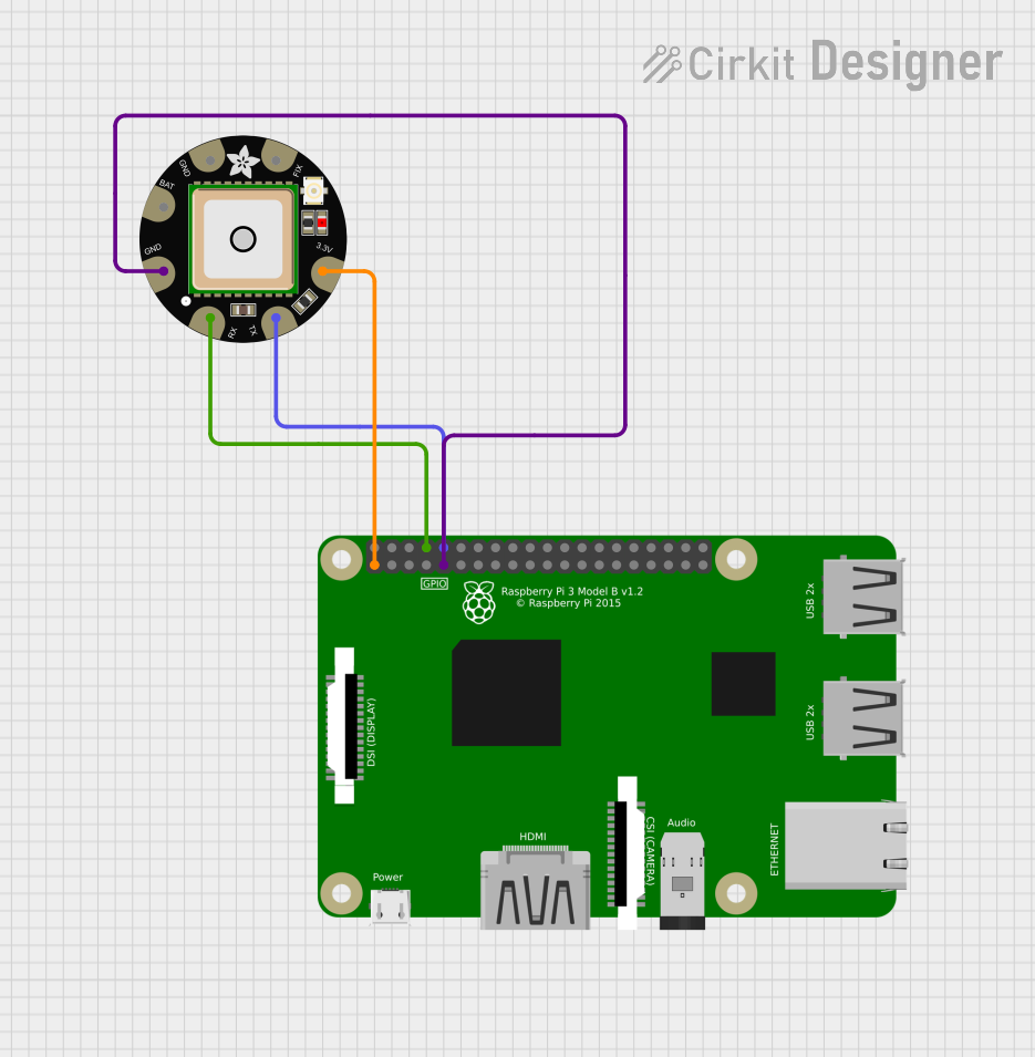
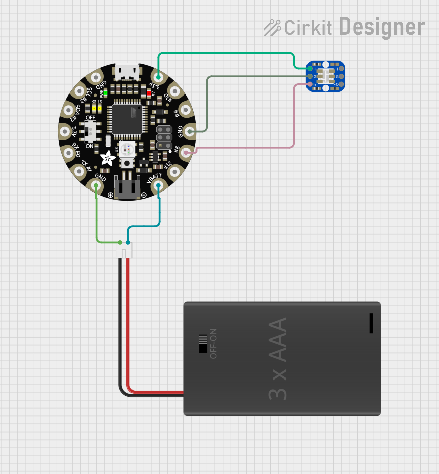


Explore Projects Built with Flora 3-Pin JST
Common Applications and Use Cases
- Wearable electronics
- Quick prototyping
- Connecting sensors to microcontrollers
- LED connections for e-textiles
- Modular electronic systems
Technical Specifications
Key Technical Details
- Voltage Rating: 3.3V to 5V (depending on the connected device)
- Current Rating: Up to 1A (depending on the connected device)
- Connector Type: JST PH 3-pin
- Wire Gauge Compatibility: 26-30 AWG
Pin Configuration and Descriptions
| Pin Number | Description | Notes |
|---|---|---|
| 1 | Power (VCC) | Typically 3.3V or 5V |
| 2 | Data/Control | Signal line (e.g., I2C, GPIO) |
| 3 | Ground (GND) | Common ground reference |
Usage Instructions
How to Use the Component in a Circuit
- Identify the Pins: Ensure you have correctly identified the VCC, Data/Control, and GND pins on the Flora 3-Pin JST connector.
- Connect to Flora Board: Align the connector with the corresponding JST port on the Flora board and gently insert it.
- Connect Peripherals: Attach the other end of the connector to your peripheral device, ensuring the correct orientation of the pins.
- Secure the Connection: Make sure the connection is firm and secure to prevent any disconnections during movement, especially in wearable applications.
Important Considerations and Best Practices
- Polarity: Always check the polarity of the connections. Reversing VCC and GND can damage the connected components.
- Current Limitations: Do not exceed the current rating of the connector to avoid overheating and potential damage.
- Signal Integrity: For signal lines, ensure that the length of the wire is appropriate to prevent signal degradation, especially in high-speed applications.
- Strain Relief: Provide strain relief for the wires connected to the JST connector to prevent mechanical stress that could lead to disconnections or damage.
Troubleshooting and FAQs
Common Issues Users Might Face
- Loose Connections: If the connector does not make a secure connection, check for any physical damage or misalignment in the pins.
- Intermittent Connectivity: Ensure that the wires are properly inserted into the connector and that there is no corrosion on the contacts.
- Incorrect Wiring: Double-check the wiring against the pin configuration to ensure that VCC, Data/Control, and GND are correctly connected.
Solutions and Tips for Troubleshooting
- Re-seat the Connector: If the connection is loose, gently remove the connector and re-insert it, ensuring it is fully seated.
- Inspect for Damage: Look for any signs of wear, bent pins, or damage to the connector and replace it if necessary.
- Test with a Multimeter: Use a multimeter to check for continuity and proper voltage levels on the pins to ensure the integrity of the connections.
FAQs
Q: Can I use the Flora 3-Pin JST connector with other microcontrollers? A: Yes, the connector is compatible with any microcontroller that supports JST PH 3-pin connections, provided the voltage and current requirements are met.
Q: Is soldering required to use this connector? A: No, the Flora 3-Pin JST is designed for plug-and-play use, and no soldering is required when connecting it to the Flora board or compatible peripherals.
Q: How do I know if the connector is properly connected to the Flora board? A: The connector should fit snugly without any wobble, and the connection should be stable without any intermittent disconnections.
Q: What wire gauge should I use with the Flora 3-Pin JST connector? A: The connector is compatible with 26-30 AWG wires. Choose the appropriate gauge based on the current requirements of your application.
Example Code for Arduino UNO
// Example code for controlling an LED using Flora 3-Pin JST connector with Arduino UNO

const int ledPin = 6; // Connect the data/control pin of the JST connector to pin 6

void setup() {
  pinMode(ledPin, OUTPUT); // Set the LED pin as an output
}

void loop() {
  digitalWrite(ledPin, HIGH); // Turn on the LED
  delay(1000);                // Wait for 1 second
  digitalWrite(ledPin, LOW);  // Turn off the LED
  delay(1000);                // Wait for 1 second
}
Remember to ensure that the LED's current and voltage requirements are compatible with the Arduino UNO's output capabilities and that the Flora 3-Pin JST connector is correctly connected to the LED and the Arduino UNO.