How to Use BD140: Examples, Pinouts, and Specs
Introduction
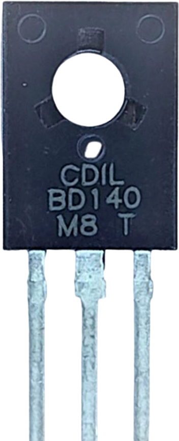
The BD140 is a PNP bipolar junction transistor (BJT) manufactured by STMicroelectronics. It is widely used in amplification and switching applications due to its robust design and reliable performance. With a maximum collector current of 1.5A and a maximum collector-emitter voltage of 60V, the BD140 is suitable for medium-power applications in audio amplifiers, motor drivers, and general-purpose switching circuits.
Explore Projects Built with BD140
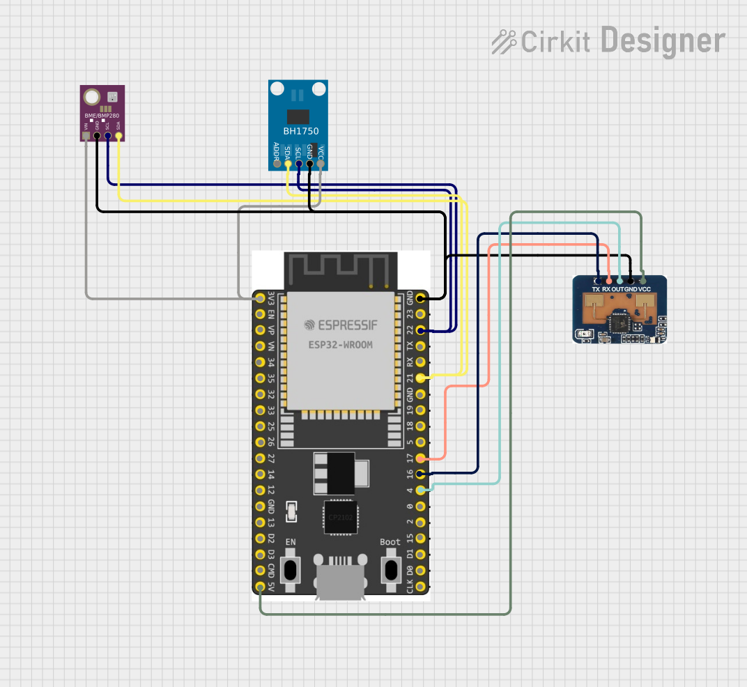
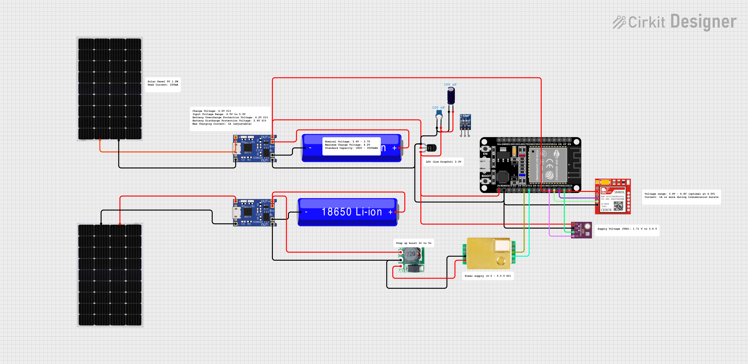
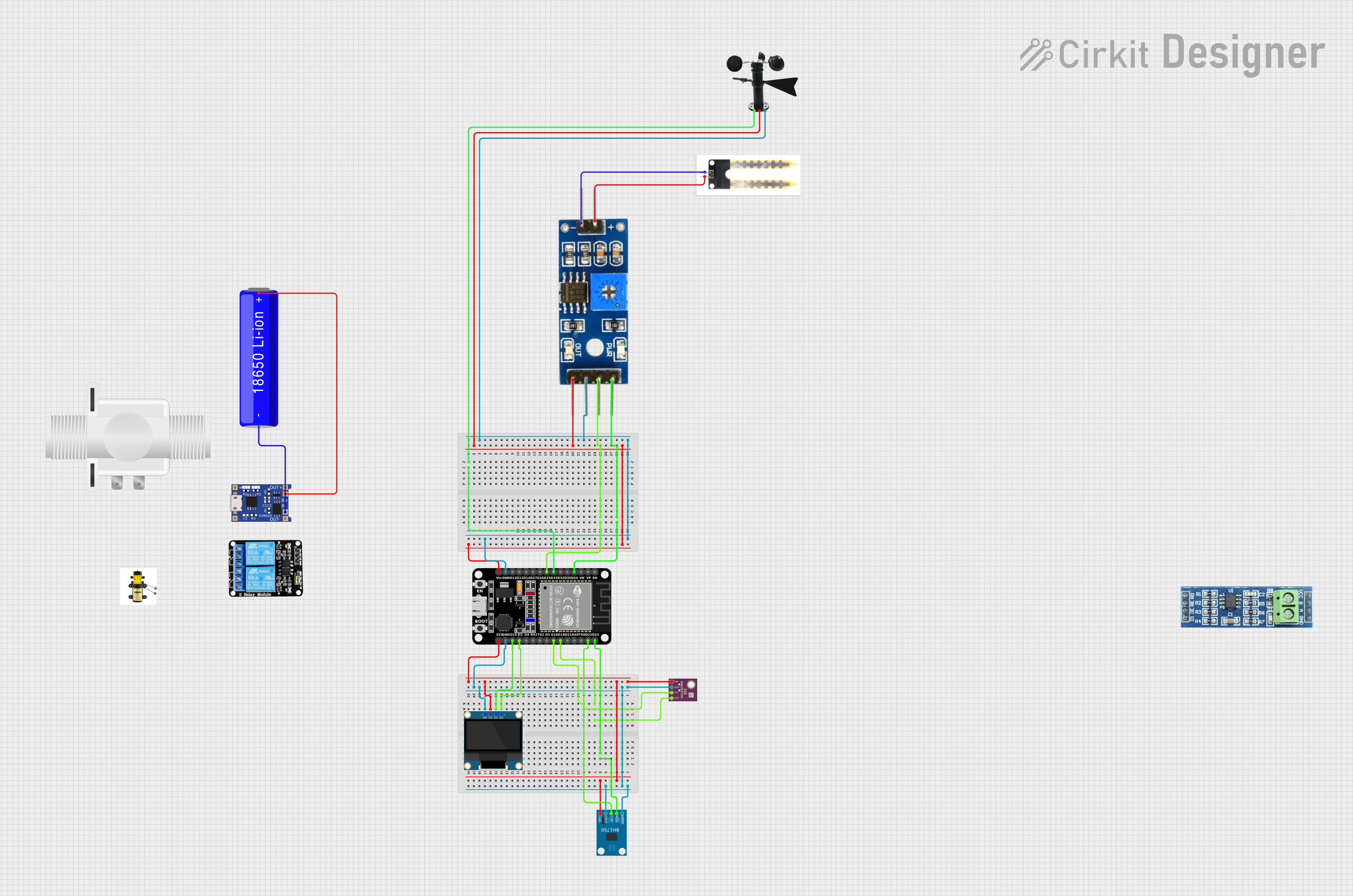
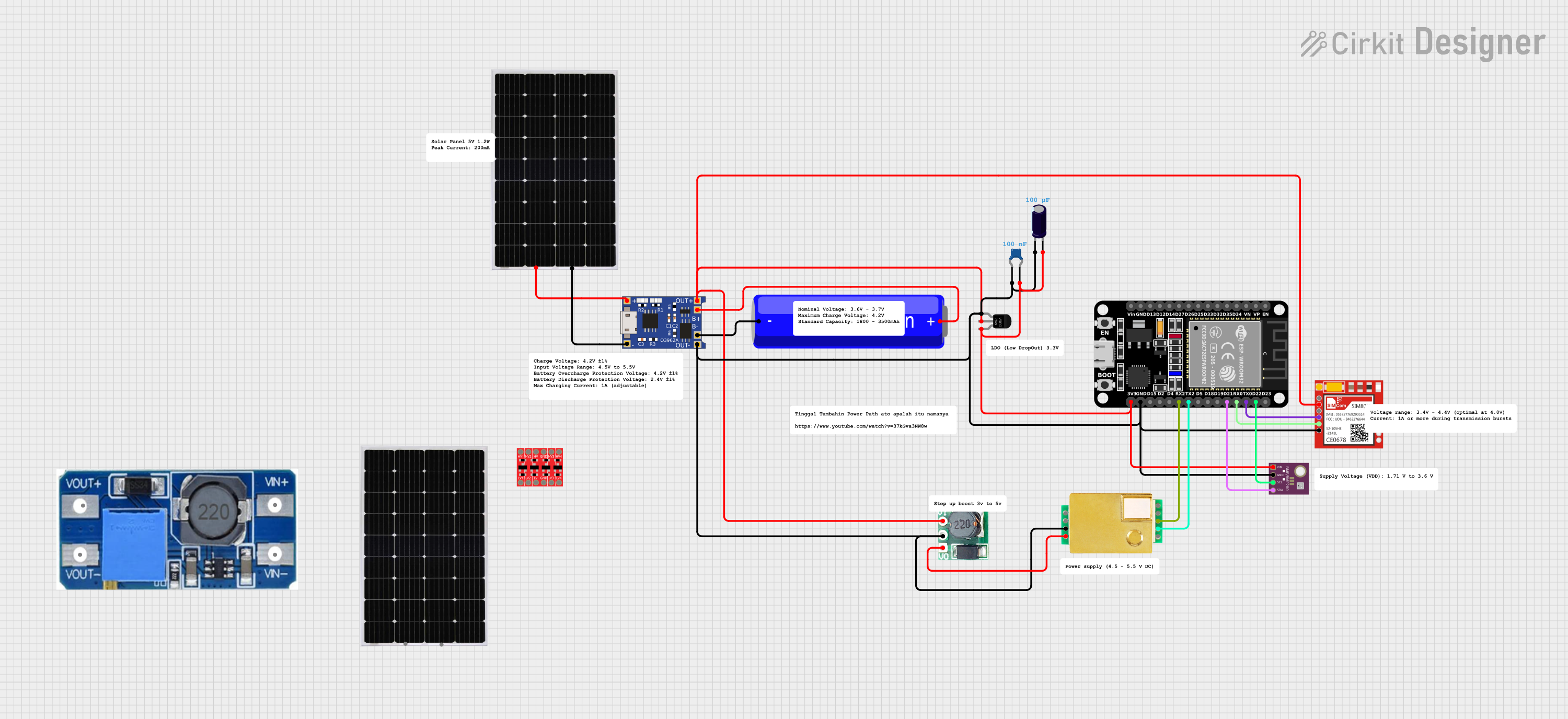
Explore Projects Built with BD140
Common Applications
- Audio amplifier circuits
- Motor control and driver circuits
- Signal amplification
- General-purpose switching in electronic devices
Technical Specifications
The BD140 transistor is designed to handle medium power levels and offers the following key specifications:
| Parameter | Value |
|---|---|
| Manufacturer | STMicroelectronics |
| Part Number | BD140 |
| Transistor Type | PNP |
| Maximum Collector-Emitter Voltage (Vce) | 60V |
| Maximum Collector-Base Voltage (Vcb) | 60V |
| Maximum Emitter-Base Voltage (Veb) | 5V |
| Maximum Collector Current (Ic) | 1.5A |
| Maximum Power Dissipation (Pd) | 12.5W (at 25°C) |
| DC Current Gain (hFE) Range | 40 to 250 |
| Transition Frequency (fT) | 190 MHz |
| Package Type | TO-126 |
| Operating Temperature Range | -55°C to +150°C |
Pin Configuration
The BD140 transistor comes in a TO-126 package with three pins. The pin configuration is as follows:
| Pin Number | Pin Name | Description |
|---|---|---|
| 1 | Emitter (E) | Current flows out of this pin |
| 2 | Collector (C) | Current flows into this pin |
| 3 | Base (B) | Controls the transistor's operation |
Usage Instructions
The BD140 transistor can be used in a variety of circuits for amplification and switching. Below are the steps and considerations for using the BD140:
Using the BD140 in a Circuit
- Determine the Configuration: Decide whether the transistor will be used in a common-emitter, common-base, or common-collector configuration based on your application.
- Base Resistor: Always use a base resistor to limit the base current and prevent damage to the transistor. The value of the resistor can be calculated using Ohm's law: [ R_b = \frac{V_{in} - V_{be}}{I_b} ] where ( V_{in} ) is the input voltage, ( V_{be} ) is the base-emitter voltage (typically 0.7V for silicon BJTs), and ( I_b ) is the desired base current.
- Collector Load: Connect a suitable load resistor or device to the collector pin. Ensure the load does not exceed the maximum collector current (1.5A).
- Power Dissipation: Ensure the total power dissipation does not exceed 12.5W. Use a heatsink if necessary to manage heat.
Example: BD140 with Arduino UNO
The BD140 can be used to control a motor or LED with an Arduino UNO. Below is an example circuit and code to control an LED:
Circuit Connections
- Connect the emitter of the BD140 to ground.
- Connect the collector to one terminal of the LED (with a current-limiting resistor in series).
- Connect the other terminal of the LED to the positive supply (e.g., 12V).
- Connect the base of the BD140 to a digital pin of the Arduino through a 1kΩ resistor.
Arduino Code
// Define the pin connected to the BD140 base
const int transistorPin = 9; // Pin 9 is used to control the BD140

void setup() {
  pinMode(transistorPin, OUTPUT); // Set the pin as an output
}

void loop() {
  digitalWrite(transistorPin, HIGH); // Turn on the LED
  delay(1000); // Wait for 1 second
  digitalWrite(transistorPin, LOW);  // Turn off the LED
  delay(1000); // Wait for 1 second
}
Best Practices
- Always check the maximum ratings to avoid damaging the transistor.
- Use a heatsink for high-power applications to prevent overheating.
- Ensure proper biasing of the base to operate the transistor in the desired region (cutoff, active, or saturation).
Troubleshooting and FAQs
Common Issues
Transistor Overheating:
- Cause: Exceeding the maximum power dissipation or insufficient cooling.
- Solution: Use a heatsink and ensure the load current is within the specified limits.
No Output Signal:
- Cause: Incorrect base resistor value or improper biasing.
- Solution: Recalculate the base resistor value and verify the base-emitter voltage.
Low Gain or Weak Amplification:
- Cause: Operating the transistor outside its hFE range.
- Solution: Ensure the base current is sufficient to achieve the desired collector current.
Transistor Not Switching:
- Cause: Insufficient base current or incorrect wiring.
- Solution: Verify the circuit connections and increase the base current if necessary.
FAQs
Q1: Can the BD140 be used for high-frequency applications?
A1: Yes, the BD140 has a transition frequency (( f_T )) of 190 MHz, making it suitable for some high-frequency applications.
Q2: What is the maximum voltage the BD140 can handle?
A2: The BD140 can handle a maximum collector-emitter voltage of 60V and a maximum collector-base voltage of 60V.
Q3: Can I use the BD140 without a heatsink?
A3: For low-power applications, a heatsink may not be necessary. However, for high-power applications, a heatsink is recommended to prevent overheating.
Q4: Is the BD140 suitable for driving relays?
A4: Yes, the BD140 can drive relays as long as the relay's current and voltage requirements are within the transistor's specifications.
By following this documentation, you can effectively use the BD140 transistor in your electronic projects.