How to Use MAX6675: Examples, Pinouts, and Specs
Introduction
The MAX6675 is a digital temperature sensor designed to work with K-type thermocouples, providing accurate temperature readings in the range of 0°C to +1024°C. It features a built-in 12-bit analog-to-digital converter (ADC) and communicates with microcontrollers via the SPI (Serial Peripheral Interface) protocol. The MAX6675 is widely used in applications requiring precise temperature monitoring, such as industrial equipment, HVAC systems, and laboratory instruments.
Explore Projects Built with MAX6675


Explore Projects Built with MAX6675
Common Applications:
- Industrial temperature monitoring
- HVAC (Heating, Ventilation, and Air Conditioning) systems
- Laboratory and scientific instruments
- Food processing and storage systems
- 3D printers and other thermal control systems
Technical Specifications
Below are the key technical details of the MAX6675:
| Parameter | Value |
|---|---|
| Operating Voltage | 3.0V to 5.5V |
| Temperature Range | 0°C to +1024°C |
| Temperature Resolution | 0.25°C |
| Communication Interface | SPI |
| ADC Resolution | 12-bit |
| Power Consumption | 1.5mA (typical) |
| Thermocouple Compatibility | K-type |
| Conversion Time | 0.22 seconds (typical) |
Pin Configuration and Descriptions
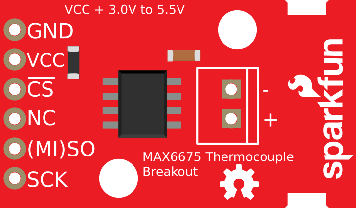
The MAX6675 is typically available in an 8-pin SOIC package. Below is the pinout and description:
| Pin | Name | Description |
|---|---|---|
| 1 | SO | Serial data output (SPI interface). Outputs temperature data in 12-bit format. |
| 2 | CS | Chip Select. Active low; enables communication with the MAX6675. |
| 3 | CLK | Serial clock input (SPI interface). Used to synchronize data transfer. |
| 4 | GND | Ground. Connect to the system ground. |
| 5 | T- | Negative terminal of the K-type thermocouple. |
| 6 | T+ | Positive terminal of the K-type thermocouple. |
| 7 | NC | No connection. Leave unconnected. |
| 8 | VCC | Power supply input (3.0V to 5.5V). |
Usage Instructions
How to Use the MAX6675 in a Circuit
- Power Supply: Connect the VCC pin to a 3.3V or 5V power source and the GND pin to the system ground.
- Thermocouple Connection: Attach the K-type thermocouple to the T+ and T- pins. Ensure proper polarity.
- SPI Communication:
- Connect the
SOpin to the MISO (Master In Slave Out) pin of the microcontroller. - Connect the
CSpin to a digital output pin on the microcontroller for chip selection. - Connect the
CLKpin to the SPI clock pin of the microcontroller.
- Connect the
- Pull-Up Resistor: No pull-up resistors are required for the SPI lines.
- Software Configuration: Use the SPI library of your microcontroller to read temperature data from the MAX6675.
Important Considerations and Best Practices
- Thermocouple Placement: Ensure the thermocouple is securely attached to the surface or environment being measured for accurate readings.
- Noise Reduction: Use short, shielded wires for the thermocouple to minimize noise interference.
- Cold-Junction Compensation: The MAX6675 includes built-in cold-junction compensation, so no external compensation is required.
- SPI Timing: Ensure the SPI clock frequency does not exceed 4.3 MHz for reliable communication.
- Thermocouple Type: Only use K-type thermocouples with the MAX6675.
Example Code for Arduino UNO
Below is an example of how to interface the MAX6675 with an Arduino UNO:
#include <SPI.h> // Include the SPI library

// Define MAX6675 pins
const int CS_PIN = 10; // Chip Select pin
const int CLK_PIN = 13; // Clock pin
const int SO_PIN = 12;  // Serial Output pin

void setup() {
  Serial.begin(9600); // Initialize serial communication
  pinMode(CS_PIN, OUTPUT); // Set CS pin as output
  digitalWrite(CS_PIN, HIGH); // Set CS pin high (inactive)
  SPI.begin(); // Initialize SPI communication
}

float readTemperature() {
  uint16_t value = 0;

  // Start communication with MAX6675
  digitalWrite(CS_PIN, LOW); // Activate the chip
  delay(1); // Small delay for stability

  // Read 16 bits of data from the MAX6675
  value = SPI.transfer(0x00); // Read the first byte
  value <<= 8; // Shift the first byte to the high byte
  value |= SPI.transfer(0x00); // Read the second byte

  digitalWrite(CS_PIN, HIGH); // Deactivate the chip

  // Check for thermocouple connection error
  if (value & 0x0004) {
    return NAN; // Return NaN if no thermocouple is connected
  }

  // Extract temperature data (bits 3 to 14) and convert to Celsius
  value >>= 3; // Shift right to remove unused bits
  return value * 0.25; // Multiply by 0.25 to get temperature in Celsius
}

void loop() {
  float temperature = readTemperature(); // Read temperature
  if (isnan(temperature)) {
    Serial.println("Thermocouple not connected!");
  } else {
    Serial.print("Temperature: ");
    Serial.print(temperature);
    Serial.println(" °C");
  }
  delay(1000); // Wait 1 second before the next reading
}
Troubleshooting and FAQs
Common Issues
No Temperature Reading:
- Cause: Thermocouple not connected or connected incorrectly.
- Solution: Verify the thermocouple is securely connected to the T+ and T- pins with correct polarity.
Incorrect Temperature Values:
- Cause: Electrical noise or incorrect SPI configuration.
- Solution: Use shielded cables for the thermocouple and ensure SPI settings (clock polarity and phase) match the MAX6675 requirements.
Thermocouple Error Flag:
- Cause: Open thermocouple or damaged sensor.
- Solution: Check the thermocouple for continuity and replace if necessary.
No SPI Communication:
- Cause: Incorrect wiring or SPI clock frequency too high.
- Solution: Verify connections and ensure the SPI clock frequency is below 4.3 MHz.
FAQs
Can I use a thermocouple other than K-type?
- No, the MAX6675 is specifically designed for K-type thermocouples.
What is the maximum cable length for the thermocouple?
- The maximum length depends on the environment and cable shielding. For best results, use shielded cables and keep the length as short as possible.
Does the MAX6675 support negative temperatures?
- No, the MAX6675 only measures temperatures in the range of 0°C to +1024°C.
Can I use the MAX6675 with a 3.3V microcontroller?
- Yes, the MAX6675 operates with a supply voltage of 3.0V to 5.5V, making it compatible with 3.3V systems.
By following this documentation, you can effectively integrate the MAX6675 into your projects for precise temperature monitoring.