How to Use Rotary Encoder: Examples, Pinouts, and Specs
Introduction
A rotary encoder is an electromechanical device that converts the angular position or motion of a shaft or axle into an analog or digital signal. Manufactured by SparkFun, this component is widely used for position sensing and control in various applications. Rotary encoders are commonly found in devices such as volume knobs, motor control systems, robotics, and user interface controls.
Rotary encoders are particularly valued for their ability to provide precise feedback on rotational movement, making them essential in applications requiring accurate position tracking or incremental adjustments.
Explore Projects Built with Rotary Encoder
Explore Projects Built with Rotary Encoder
Technical Specifications
Below are the key technical details for the SparkFun Rotary Encoder:
- Operating Voltage: 3.3V to 5V
- Output Type: Digital (Quadrature signals: A and B)
- Resolution: 20 pulses per revolution (PPR)
- Switch Type: Momentary push-button (optional)
- Debouncing: Required for stable signal processing
- Mounting Type: PCB mount
- Shaft Diameter: 6mm
- Operating Temperature: -40°C to 85°C
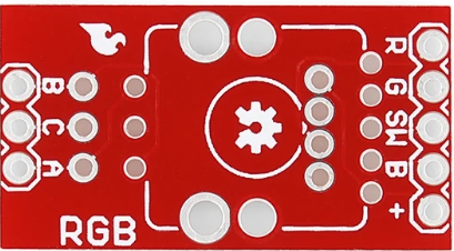
Pin Configuration and Descriptions
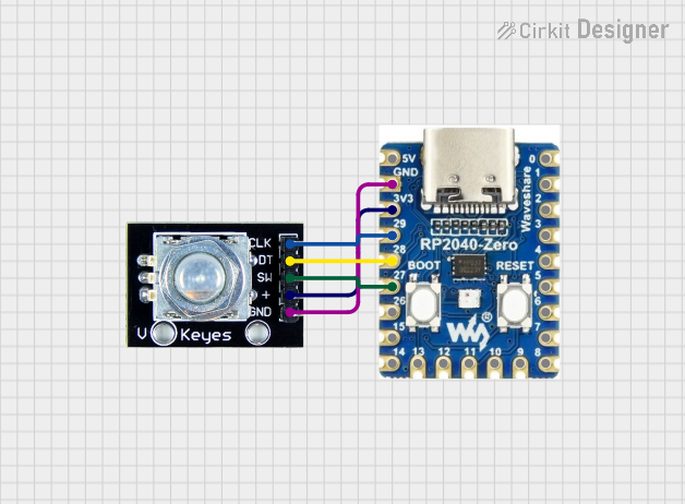
The SparkFun Rotary Encoder typically has 5 pins. The table below describes each pin:
| Pin Name | Description |
|---|---|
| CLK | Clock signal output (Channel A) - Provides one of the quadrature signals. |
| DT | Data signal output (Channel B) - Provides the second quadrature signal. |
| SW | Push-button switch output - Active LOW when the shaft is pressed. |
| VCC | Power supply input - Connect to 3.3V or 5V. |
| GND | Ground connection - Connect to the ground of the circuit. |
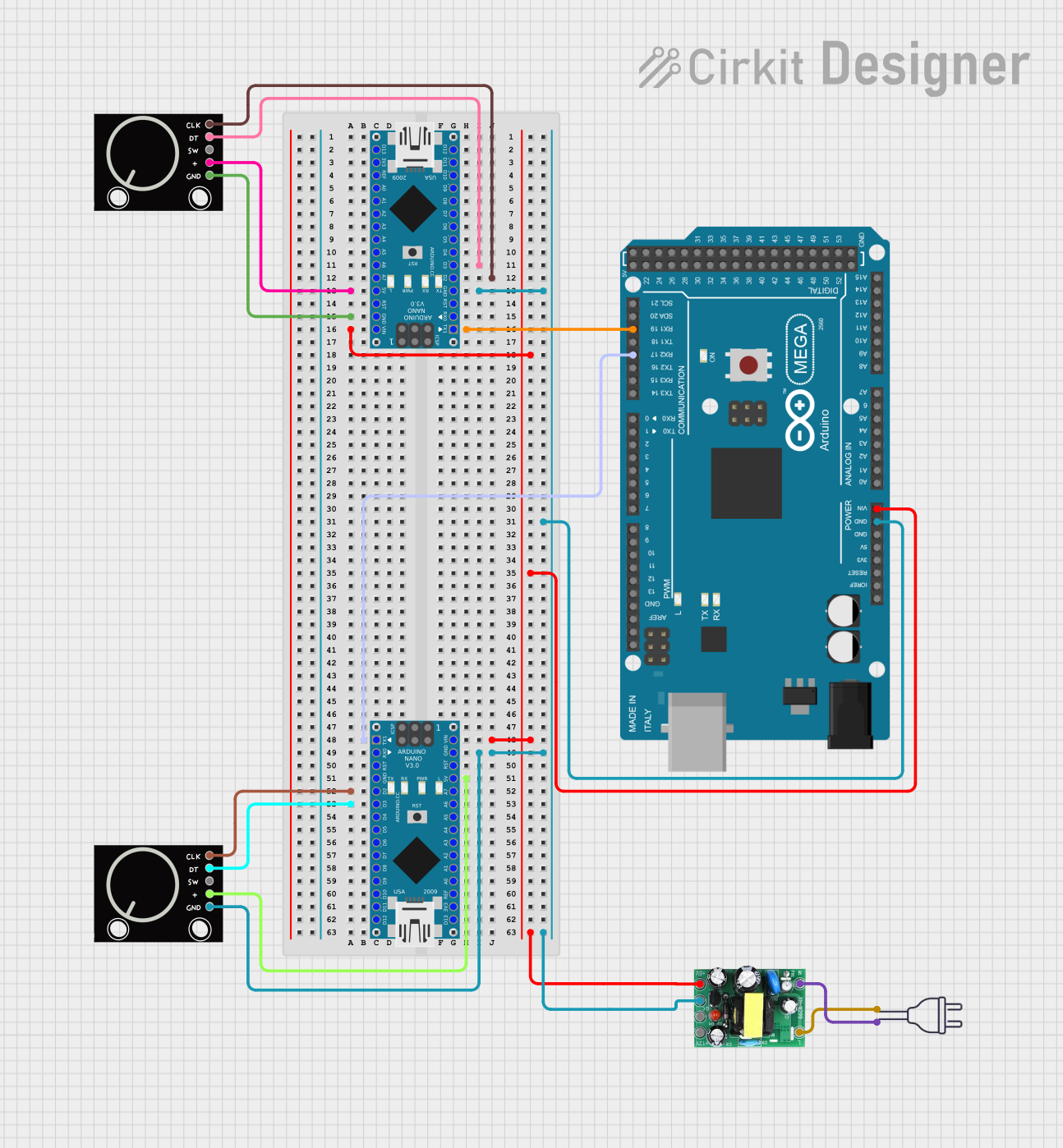
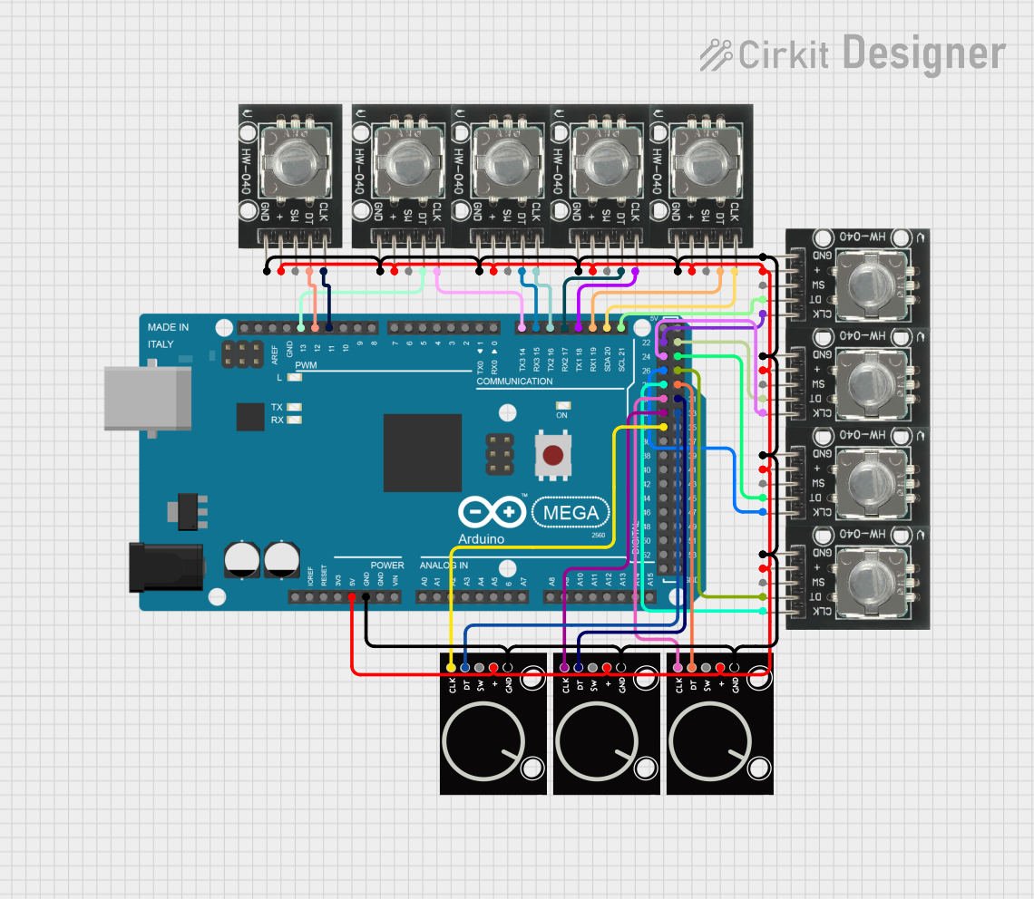
Usage Instructions
How to Use the Rotary Encoder in a Circuit
Wiring the Encoder:
- Connect the VCC pin to a 3.3V or 5V power source.
- Connect the GND pin to the ground of your circuit.
- Connect the CLK and DT pins to two digital input pins on your microcontroller.
- Optionally, connect the SW pin to another digital input pin if you want to use the push-button feature.
Reading the Encoder:
- The rotary encoder outputs two quadrature signals (CLK and DT). By monitoring the sequence of these signals, you can determine the direction of rotation and the number of steps moved.
- The push-button switch can be used for additional functionality, such as resetting a counter or triggering an action.
Debouncing:
- Rotary encoders often produce noisy signals due to mechanical contacts. Use hardware (capacitors) or software (debouncing algorithms) to filter out noise and ensure stable readings.
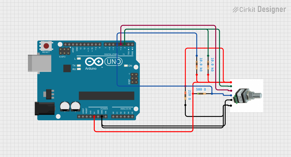
Arduino UNO Example Code
Below is an example of how to use the SparkFun Rotary Encoder with an Arduino UNO:
// Rotary Encoder Example Code for Arduino UNO
// Connect CLK to pin 2, DT to pin 3, and SW to pin 4

#define CLK 2  // Clock signal (Channel A)
#define DT 3   // Data signal (Channel B)
#define SW 4   // Push-button switch

int lastStateCLK;  // To store the previous state of the CLK pin
int currentStateCLK;  // To store the current state of the CLK pin
int counter = 0;  // Counter to track encoder position
bool buttonPressed = false;  // To track the state of the push-button

void setup() {
  pinMode(CLK, INPUT);
  pinMode(DT, INPUT);
  pinMode(SW, INPUT_PULLUP);  // Use internal pull-up resistor for the switch
  Serial.begin(9600);

  // Initialize the last state of CLK
  lastStateCLK = digitalRead(CLK);
}

void loop() {
  // Read the current state of the CLK pin
  currentStateCLK = digitalRead(CLK);

  // If the state of CLK has changed, check the direction of rotation
  if (currentStateCLK != lastStateCLK) {
    // If DT state is different from CLK state, the encoder is rotating CW
    if (digitalRead(DT) != currentStateCLK) {
      counter++;
    } else {
      counter--;
    }

    // Print the counter value to the Serial Monitor
    Serial.print("Position: ");
    Serial.println(counter);
  }

  // Update the last state of CLK
  lastStateCLK = currentStateCLK;

  // Check if the push-button is pressed
  if (digitalRead(SW) == LOW) {
    if (!buttonPressed) {
      Serial.println("Button Pressed!");
      buttonPressed = true;
    }
  } else {
    buttonPressed = false;
  }
}
Important Considerations and Best Practices
- Power Supply: Ensure the rotary encoder is powered within its operating voltage range (3.3V to 5V).
- Debouncing: Use capacitors or software techniques to debounce the signals for accurate readings.
- Signal Monitoring: Use interrupts for real-time signal monitoring in applications requiring high precision.
- Mechanical Durability: Avoid applying excessive force to the shaft to prevent damage.
Troubleshooting and FAQs
Common Issues and Solutions
No Signal Output:
- Ensure the encoder is properly connected to the power supply and ground.
- Verify that the CLK and DT pins are connected to the correct microcontroller pins.
Unstable or Noisy Readings:
- Add a 0.1µF capacitor between the CLK/DT pins and ground to reduce noise.
- Implement software debouncing in your code.
Push-Button Not Working:
- Check the connection of the SW pin and ensure it is configured as an input with a pull-up resistor.
- Verify that the button is not physically damaged.
Incorrect Direction Detection:
- Swap the connections of the CLK and DT pins to correct the direction.
FAQs
Q: Can I use the rotary encoder with a 3.3V microcontroller?
A: Yes, the SparkFun Rotary Encoder is compatible with both 3.3V and 5V systems.
Q: How do I increase the resolution of the encoder?
A: The resolution is determined by the encoder's design (20 PPR for this model). To achieve higher resolution, consider using a different encoder with a higher PPR rating.
Q: Can I use the encoder for continuous rotation?
A: Yes, the rotary encoder supports continuous rotation and provides incremental feedback for each step.
Q: Do I need external pull-up resistors for the push-button?
A: No, you can use the internal pull-up resistor of the microcontroller by configuring the pin as INPUT_PULLUP.
By following this documentation, you can effectively integrate the SparkFun Rotary Encoder into your projects for precise position sensing and control.