How to Use Sensor encoder: Examples, Pinouts, and Specs
Introduction
A sensor encoder is a device that converts physical motion or position into an electrical signal. It is widely used in robotics, automation, and industrial applications to provide precise feedback on the position, speed, or direction of a moving part. By translating mechanical motion into electrical signals, sensor encoders enable accurate control and monitoring of systems such as robotic arms, conveyor belts, and motorized equipment.
Explore Projects Built with Sensor encoder
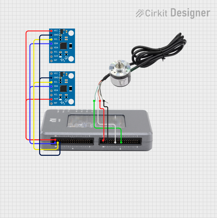
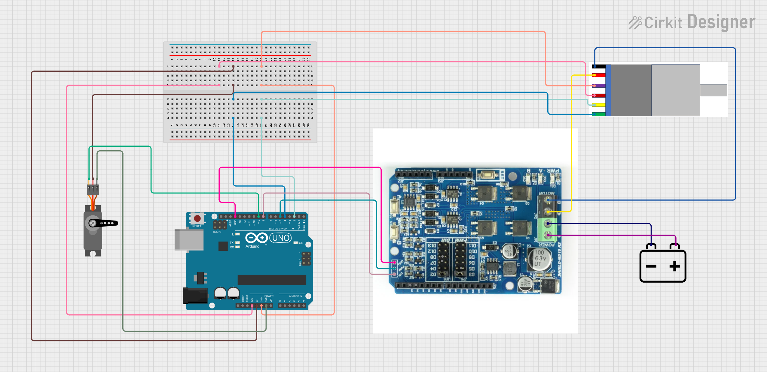


Explore Projects Built with Sensor encoder
Common Applications and Use Cases
- Robotics: Position and motion feedback for robotic arms and mobile robots.
- Industrial Automation: Monitoring and controlling conveyor belts, motors, and actuators.
- CNC Machines: Ensuring precise positioning of tools and workpieces.
- 3D Printers: Tracking the movement of print heads and build platforms.
- Elevators: Detecting the position of the elevator car for smooth operation.
Technical Specifications
Key Technical Details
- Operating Voltage: 3.3V to 5V DC
- Output Signal: Digital (Quadrature or Single Pulse)
- Resolution: 100 to 10,000 pulses per revolution (PPR), depending on the model
- Maximum Rotational Speed: Up to 10,000 RPM
- Output Format: A/B channels (quadrature) or single-channel pulse
- Operating Temperature: -20°C to 85°C
- Connector Type: 3-pin or 4-pin (depending on the model)
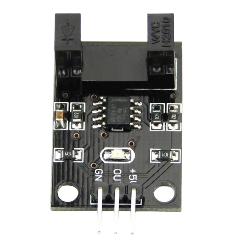
Pin Configuration and Descriptions
Below is the pin configuration for a typical 4-pin sensor encoder:
| Pin | Name | Description |
|---|---|---|
| 1 | VCC | Power supply input (3.3V to 5V DC). |
| 2 | GND | Ground connection. |
| 3 | A (Signal) | Output signal for channel A (used in quadrature encoding). |
| 4 | B (Signal) | Output signal for channel B (used in quadrature encoding for direction sensing). |
For a 3-pin encoder, the configuration is as follows:
| Pin | Name | Description |
|---|---|---|
| 1 | VCC | Power supply input (3.3V to 5V DC). |
| 2 | GND | Ground connection. |
| 3 | Signal | Output signal (single-channel pulse). |
Usage Instructions
How to Use the Sensor Encoder in a Circuit
- Connect Power:
- Connect the VCC pin to a 3.3V or 5V power source.
- Connect the GND pin to the ground of your circuit.
- Connect Signal Pins:
- For a quadrature encoder, connect the A and B signal pins to digital input pins on your microcontroller.
- For a single-channel encoder, connect the Signal pin to a digital input pin.
- Read the Output:
- Monitor the signal pins to detect pulses. For quadrature encoders, use both A and B channels to determine direction and speed.
- Debounce the Signal:
- Use hardware or software debouncing to filter out noise and ensure accurate readings.
Important Considerations and Best Practices
- Power Supply: Ensure the encoder operates within its specified voltage range to avoid damage.
- Pull-Up Resistors: Some encoders may require external pull-up resistors on the signal lines.
- Mounting: Secure the encoder firmly to prevent misalignment or vibration, which can affect accuracy.
- Cable Length: Minimize the length of signal cables to reduce noise and signal degradation.
- Direction Detection: For quadrature encoders, ensure your code correctly interprets the phase difference between A and B channels.
Example Code for Arduino UNO
Below is an example of how to use a quadrature encoder with an Arduino UNO:
// Example code for reading a quadrature encoder with Arduino UNO
// Connect encoder A and B pins to digital pins 2 and 3 on the Arduino

#define ENCODER_PIN_A 2  // Pin connected to encoder channel A
#define ENCODER_PIN_B 3  // Pin connected to encoder channel B

volatile int encoderPosition = 0;  // Variable to store encoder position

void setup() {
  pinMode(ENCODER_PIN_A, INPUT);  // Set channel A as input
  pinMode(ENCODER_PIN_B, INPUT);  // Set channel B as input

  // Attach interrupts to handle encoder signals
  attachInterrupt(digitalPinToInterrupt(ENCODER_PIN_A), encoderISR, CHANGE);

  Serial.begin(9600);  // Initialize serial communication
}

void loop() {
  // Print the current encoder position
  Serial.print("Encoder Position: ");
  Serial.println(encoderPosition);
  delay(100);  // Delay for readability
}

// Interrupt Service Routine (ISR) for encoder
void encoderISR() {
  // Read the state of channel A and B
  int stateA = digitalRead(ENCODER_PIN_A);
  int stateB = digitalRead(ENCODER_PIN_B);

  // Determine direction based on the state of A and B
  if (stateA == stateB) {
    encoderPosition++;  // Clockwise rotation
  } else {
    encoderPosition--;  // Counterclockwise rotation
  }
}
Troubleshooting and FAQs
Common Issues and Solutions
No Signal Output:
- Cause: Incorrect wiring or insufficient power supply.
- Solution: Double-check all connections and ensure the power supply voltage matches the encoder's requirements.
Inaccurate Readings:
- Cause: Signal noise or misalignment of the encoder.
- Solution: Use shielded cables, add pull-up resistors, and ensure the encoder is securely mounted.
Direction Detection Not Working:
- Cause: Incorrect interpretation of A and B channel signals.
- Solution: Verify the phase relationship between A and B channels and adjust your code accordingly.
Signal Fluctuations:
- Cause: Mechanical vibrations or poor signal debouncing.
- Solution: Implement software debouncing or use hardware filters.
FAQs
Q: Can I use a sensor encoder with a Raspberry Pi?
- A: Yes, but ensure you use GPIO pins with appropriate pull-up resistors and handle interrupts carefully.
Q: What is the difference between single-channel and quadrature encoders?
- A: Single-channel encoders provide only pulse counts, while quadrature encoders provide both pulse counts and direction information.
Q: How do I calculate speed using a sensor encoder?
- A: Measure the time between pulses and use the encoder's resolution (PPR) to calculate speed.
By following this documentation, you can effectively integrate a sensor encoder into your projects and troubleshoot common issues.