Cirkit Designer Logo
Cirkit Designer
Your all-in-one circuit design IDE
Home / 
Component Documentation

How to Use Grove gps (Air 530): Examples, Pinouts, and Specs

Image of Grove gps (Air 530)
Cirkit Designer LogoDesign with Grove gps (Air 530) in Cirkit Designer

Introduction

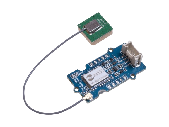
The Grove GPS (Air 530) is a high-performance GPS module manufactured by SeeedStudio. It is designed for precise location tracking and features a compact design, making it ideal for outdoor navigation and location-based applications. The module supports multiple satellite navigation systems, including GPS, BeiDou, and QZSS, ensuring reliable and accurate positioning. Its Grove-compatible interface allows for seamless integration with microcontrollers, such as Arduino and Raspberry Pi, making it a versatile choice for developers and hobbyists.

Explore Projects Built with Grove gps (Air 530)

Use Cirkit Designer to design, explore, and prototype these projects online. Some projects support real-time simulation. Click "Open Project" to start designing instantly!
ESP32-Based GPS Tracker with OLED Display and Telegram Integration
Image of Yoon: A project utilizing Grove gps (Air 530) in a practical application
This circuit is a GPS-based tracking system that uses an ESP32 microcontroller to receive GPS data from a NEO 6M module and display the coordinates on a 1.3" OLED screen. It also features WiFi connectivity to send location updates to a remote server, potentially for applications such as asset tracking or navigation assistance.
Cirkit Designer LogoOpen Project in Cirkit Designer
Arduino UNO with A9G GSM/GPRS and Dual VL53L1X Distance Sensors
Image of TED CIRCUIT : A project utilizing Grove gps (Air 530) in a practical application
This circuit features an Arduino UNO microcontroller interfaced with an A9G GSM/GPRS+GPS/BDS module and two VL53L1X time-of-flight distance sensors. The A9G module is connected to the Arduino via serial communication for GPS and GSM functionalities, while both VL53L1X sensors are connected through I2C with shared SDA and SCL lines and individual SHUT pins for selective sensor activation. The Arduino is programmed to control these peripherals, although the specific functionality is not detailed in the provided code.
Cirkit Designer LogoOpen Project in Cirkit Designer
Arduino Nano GPS Tracker with GSM and OLED Display
Image of Smart GPS Tracker: A project utilizing Grove gps (Air 530) in a practical application
This circuit is a GPS tracking system that uses an Arduino Nano to interface with a SIM800L GSM module, a GPS NEO 6M module, and a 1.3-inch OLED display. The Arduino collects GPS data, displays it on the OLED screen, and sends the coordinates via SMS using the GSM module.
Cirkit Designer LogoOpen Project in Cirkit Designer
Arduino UNO Based GPS and GSM Tracking System
Image of priyanka rakshe: A project utilizing Grove gps (Air 530) in a practical application
This circuit features an Arduino UNO microcontroller connected to an Adafruit Ultimate GPS v3 module for receiving GPS data. The GPS module is powered by the Arduino's 5V output and communicates via serial connection using the TX and RX pins connected to the Arduino's digital pins D4 and D3, respectively. The microcontroller's code structure is set up with empty setup() and loop() functions, ready for implementing the logic to interact with the GPS module.
Cirkit Designer LogoOpen Project in Cirkit Designer

Explore Projects Built with Grove gps (Air 530)

Use Cirkit Designer to design, explore, and prototype these projects online. Some projects support real-time simulation. Click "Open Project" to start designing instantly!
Image of Yoon: A project utilizing Grove gps (Air 530) in a practical application
ESP32-Based GPS Tracker with OLED Display and Telegram Integration
This circuit is a GPS-based tracking system that uses an ESP32 microcontroller to receive GPS data from a NEO 6M module and display the coordinates on a 1.3" OLED screen. It also features WiFi connectivity to send location updates to a remote server, potentially for applications such as asset tracking or navigation assistance.
Cirkit Designer LogoOpen Project in Cirkit Designer
Image of TED CIRCUIT : A project utilizing Grove gps (Air 530) in a practical application
Arduino UNO with A9G GSM/GPRS and Dual VL53L1X Distance Sensors
This circuit features an Arduino UNO microcontroller interfaced with an A9G GSM/GPRS+GPS/BDS module and two VL53L1X time-of-flight distance sensors. The A9G module is connected to the Arduino via serial communication for GPS and GSM functionalities, while both VL53L1X sensors are connected through I2C with shared SDA and SCL lines and individual SHUT pins for selective sensor activation. The Arduino is programmed to control these peripherals, although the specific functionality is not detailed in the provided code.
Cirkit Designer LogoOpen Project in Cirkit Designer
Image of Smart GPS Tracker: A project utilizing Grove gps (Air 530) in a practical application
Arduino Nano GPS Tracker with GSM and OLED Display
This circuit is a GPS tracking system that uses an Arduino Nano to interface with a SIM800L GSM module, a GPS NEO 6M module, and a 1.3-inch OLED display. The Arduino collects GPS data, displays it on the OLED screen, and sends the coordinates via SMS using the GSM module.
Cirkit Designer LogoOpen Project in Cirkit Designer
Image of priyanka rakshe: A project utilizing Grove gps (Air 530) in a practical application
Arduino UNO Based GPS and GSM Tracking System
This circuit features an Arduino UNO microcontroller connected to an Adafruit Ultimate GPS v3 module for receiving GPS data. The GPS module is powered by the Arduino's 5V output and communicates via serial connection using the TX and RX pins connected to the Arduino's digital pins D4 and D3, respectively. The microcontroller's code structure is set up with empty setup() and loop() functions, ready for implementing the logic to interact with the GPS module.
Cirkit Designer LogoOpen Project in Cirkit Designer

Common Applications and Use Cases

  • Outdoor navigation systems
  • Location-based services and geofencing
  • Vehicle tracking and fleet management
  • Wearable devices for fitness and sports
  • IoT projects requiring geolocation data

Technical Specifications

The following table outlines the key technical details of the Grove GPS (Air 530):

Parameter Specification
Satellite Systems GPS, BeiDou, QZSS
Positioning Accuracy 2.5 meters CEP
Update Rate 1 Hz (default), configurable up to 10 Hz
Operating Voltage 3.3V to 5.0V
Operating Current 30 mA (typical)
Communication Interface UART (default baud rate: 9600 bps)
Operating Temperature -40°C to +85°C
Dimensions 40mm x 20mm
Weight 8 grams

Pin Configuration and Descriptions

The Grove GPS (Air 530) module has a 4-pin Grove connector. The pin configuration is as follows:

Pin Name Description
1 VCC Power supply (3.3V to 5.0V)
2 GND Ground
3 RX UART Receive (connect to TX of MCU)
4 TX UART Transmit (connect to RX of MCU)

Usage Instructions

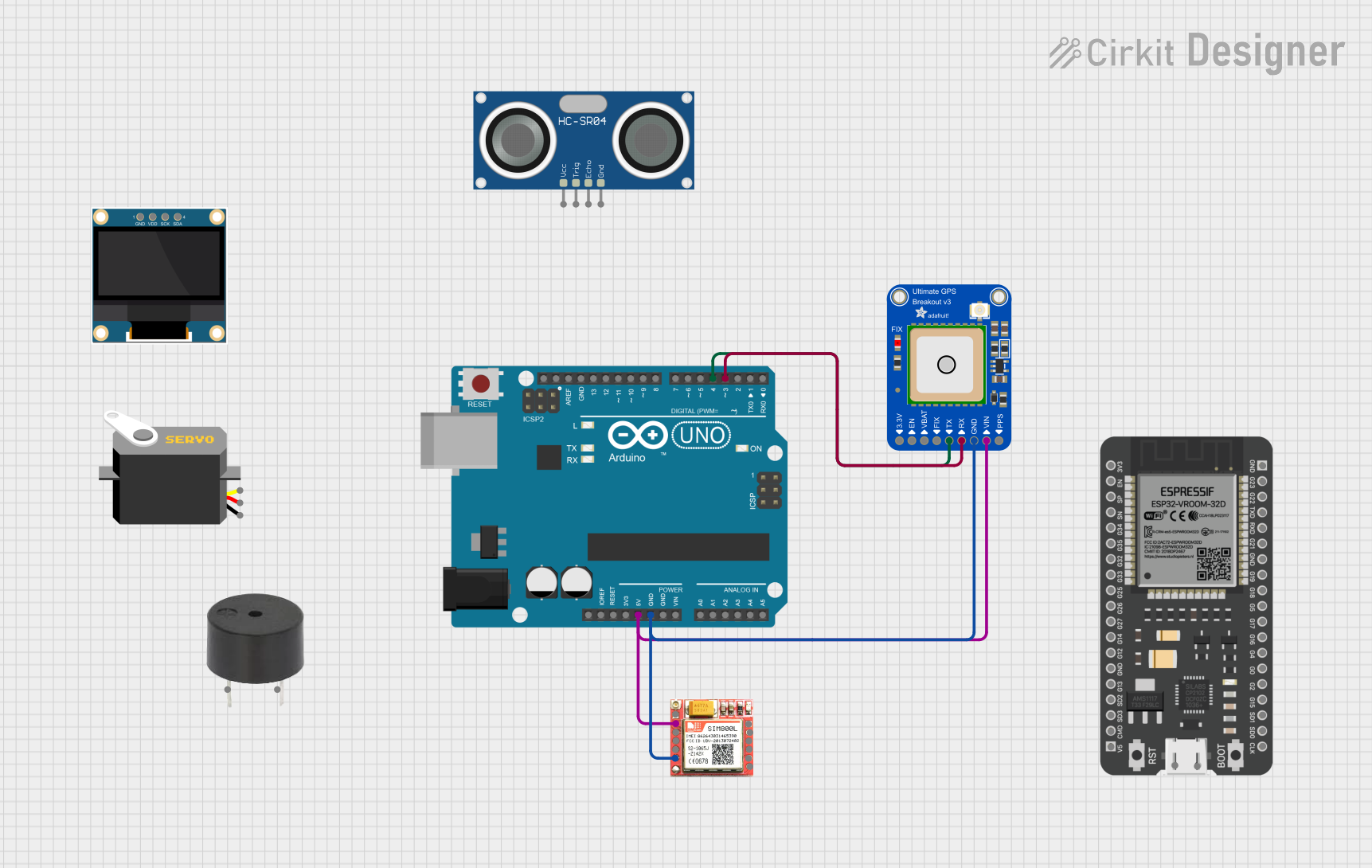
How to Use the Grove GPS (Air 530) in a Circuit

  1. Connect the Module: Use a Grove cable to connect the GPS module to a Grove Base Shield attached to your microcontroller (e.g., Arduino UNO).
  2. Power the Module: Ensure the module is powered with a voltage between 3.3V and 5.0V.
  3. Establish Communication: The module communicates via UART. Connect the RX pin of the module to the TX pin of the microcontroller and the TX pin of the module to the RX pin of the microcontroller.
  4. Read GPS Data: Use a serial monitor or write a program to parse the NMEA sentences (standard GPS data format) sent by the module.

Important Considerations and Best Practices

  • Antenna Placement: For optimal performance, ensure the module has a clear view of the sky to receive satellite signals.
  • Baud Rate Configuration: The default baud rate is 9600 bps. If needed, you can configure the baud rate using specific commands.
  • Cold Start vs. Warm Start: A cold start (first-time satellite acquisition) may take longer than a warm start (reacquisition after a short power-off period).
  • Avoid Interference: Keep the module away from sources of electromagnetic interference (e.g., high-frequency circuits).

Example Code for Arduino UNO

Below is an example code to interface the Grove GPS (Air 530) with an Arduino UNO and display GPS data on the serial monitor:

#include <SoftwareSerial.h>

// Define RX and TX pins for SoftwareSerial
SoftwareSerial gpsSerial(4, 3); // RX = Pin 4, TX = Pin 3

void setup() {
  Serial.begin(9600);          // Initialize Serial Monitor at 9600 bps
  gpsSerial.begin(9600);       // Initialize GPS module at 9600 bps
  Serial.println("Grove GPS (Air 530) Test");
}

void loop() {
  // Check if data is available from the GPS module
  while (gpsSerial.available()) {
    char c = gpsSerial.read(); // Read one character from GPS module
    Serial.print(c);           // Print the character to Serial Monitor
  }
}

Note: Ensure the RX and TX pins in the code match your hardware connections. Use a SoftwareSerial library if the hardware UART is already in use.

Troubleshooting and FAQs

Common Issues and Solutions

  1. No GPS Data Received

    • Cause: Poor satellite signal or incorrect wiring.
    • Solution: Ensure the module has a clear view of the sky and verify the connections.
  2. Garbage Characters in Serial Monitor

    • Cause: Mismatched baud rate.
    • Solution: Confirm that the baud rate of the GPS module matches the baud rate in your code (default is 9600 bps).
  3. Slow GPS Fix

    • Cause: Cold start or poor signal conditions.
    • Solution: Allow the module more time to acquire satellites, and ensure it is placed in an open area.
  4. Module Not Powering On

    • Cause: Insufficient power supply.
    • Solution: Verify that the power supply voltage is within the 3.3V to 5.0V range.

FAQs

  • Q: Can the module work indoors?

    • A: The module may work indoors near windows, but performance is significantly better outdoors with a clear view of the sky.
  • Q: How do I parse NMEA sentences?

    • A: Use libraries like TinyGPS++ or write custom code to extract latitude, longitude, and other data from NMEA sentences.
  • Q: Can I increase the update rate?

    • A: Yes, the update rate can be configured up to 10 Hz using specific commands. Refer to the module's datasheet for details.

By following this documentation, you can effectively integrate the Grove GPS (Air 530) into your projects and troubleshoot common issues.