The ESP32-S3 EC200U 4G LTE is a versatile IoT module manufactured by 7Semi (Part ID: DC-10120). It combines the powerful ESP32-S3 microcontroller with the Quectel EC200U 4G LTE modem, enabling seamless integration of Wi-Fi, Bluetooth, and cellular connectivity in a single device. This module is ideal for applications requiring reliable wireless communication, such as IoT devices, smart home systems, industrial automation, and remote monitoring.
Explore Projects Built with ESP32-S3 EC200U 4G LTE
Use Cirkit Designer to design, explore, and prototype these projects online. Some projects support real-time simulation. Click "Open Project" to start designing instantly!
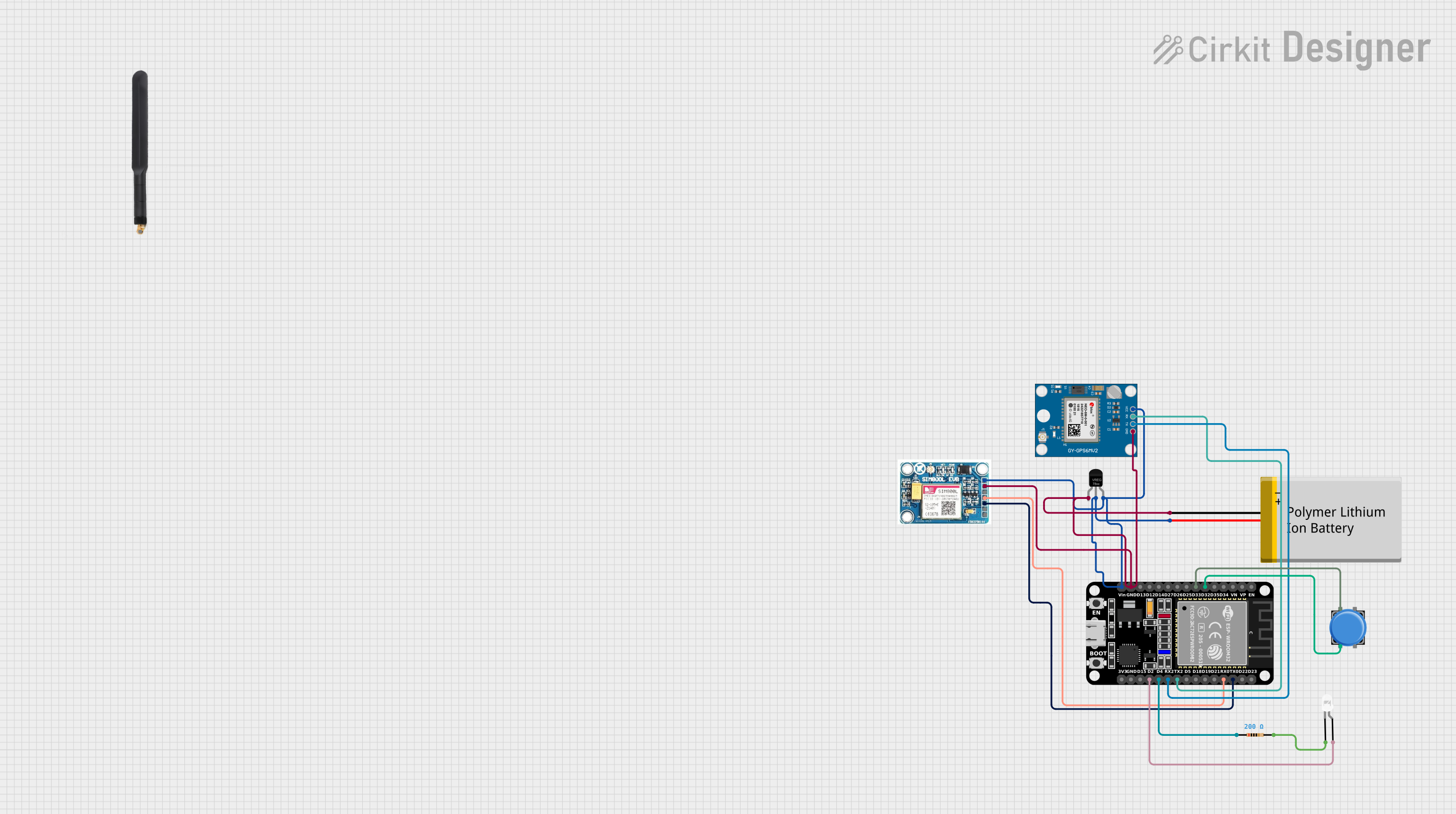
This circuit features an ESP32 microcontroller interfaced with a SIM 800L GSM module for cellular communication and a Neo 6M GPS module for location tracking. A voltage regulator is used to maintain a stable voltage supply from a polymer lithium-ion battery to the GSM, GPS, and ESP32 modules. Additionally, the circuit includes a pushbutton to trigger inputs and an LED with a current-limiting resistor, likely for status indication.
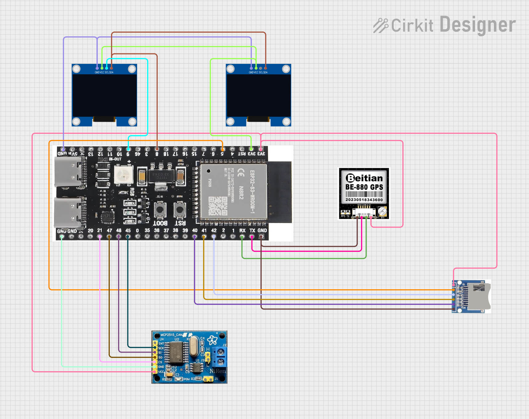
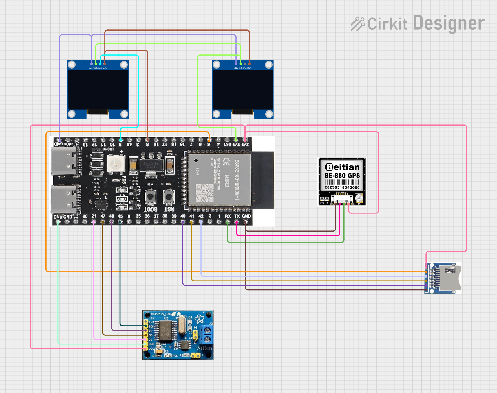
This circuit features an ESP32-S3 microcontroller interfaced with an SD card module, two OLED displays, a GPS module, and a CAN bus module. The ESP32-S3 records GPS data to the SD card, displays speed on one OLED, and shows wind speed from the CAN bus on the other OLED, providing a comprehensive data logging and display system.
This circuit features an ESP32-S3 microcontroller interfaced with an SD card, two OLED displays, a GPS module, and a CAN bus module. It records GPS data to the SD card every second, displays speed in knots on one OLED display, and shows wind speed from the CAN bus in NMEA 2000 format on the other OLED display.
This is a multi-functional ESP32-based circuit designed for location tracking and GSM communication, featuring a GPS module, a SIM800L GSM module, a vibration sensor, a buzzer, a pushbutton, and an LED indicator. It is powered by a 5V battery and includes resistors for current limiting and signal conditioning.
IoT Gateways: Facilitates data transmission between IoT devices and cloud platforms.
Smart Home Devices: Enables remote control and monitoring of smart appliances.
Industrial Automation: Provides robust connectivity for industrial sensors and controllers.
Vehicle Tracking: Supports GPS and LTE for real-time vehicle location tracking.
Remote Monitoring: Ideal for applications like weather stations and agricultural monitoring.
Technical Specifications
Key Technical Details
Parameter
Specification
Microcontroller
ESP32-S3 (Xtensa® 32-bit LX7 dual-core processor)
Cellular Modem
Quectel EC200U (4G LTE Cat 4)
Wi-Fi
802.11 b/g/n (2.4 GHz)
Bluetooth
Bluetooth 5.0 (LE)
Operating Voltage
3.3V
Power Consumption
5 µA (deep sleep), ~200 mA (active LTE transmission)
GPIO Pins
34 GPIOs (configurable for digital/analog I/O)
UART Interfaces
3 UARTs
SPI/I2C/I2S Support
Yes
LTE Bands
B1/B3/B5/B7/B8/B20/B28
GNSS Support
GPS, GLONASS, BeiDou, Galileo
Operating Temperature
-40°C to +85°C
Dimensions
50 mm x 30 mm x 5 mm
Pin Configuration and Descriptions
Pin Name
Type
Description
VIN
Power Input
3.3V power supply input.
GND
Ground
Ground connection.
TXD0
UART TX
UART0 transmit pin for serial communication.
RXD0
UART RX
UART0 receive pin for serial communication.
GPIO0
Digital I/O
General-purpose I/O pin.
GPIO1
Digital I/O
General-purpose I/O pin.
LTE_TX
UART TX
Transmit pin for LTE modem communication.
LTE_RX
UART RX
Receive pin for LTE modem communication.
ANT
RF Connector
External antenna connection for LTE/GNSS.
RESET
Input
Active-low reset pin for the module.
Usage Instructions
How to Use the Component in a Circuit
Power Supply: Connect the VIN pin to a stable 3.3V power source and GND to ground.
Serial Communication: Use the TXD0 and RXD0 pins to interface with a microcontroller or PC via UART.
LTE Antenna: Attach an external LTE antenna to the ANT pin for optimal cellular performance.
GPIO Configuration: Configure GPIO pins as needed for digital or analog input/output.
LTE Modem Communication: Use the LTE_TX and LTE_RX pins to communicate with the Quectel EC200U modem.
Reset: Connect the RESET pin to a push-button or microcontroller for manual or software-controlled resets.
Important Considerations and Best Practices
Power Stability: Ensure a clean and stable 3.3V power supply to avoid communication issues.
Antenna Placement: Position the LTE antenna away from noise sources for better signal quality.
Firmware Updates: Regularly update the ESP32-S3 firmware to ensure compatibility and security.
Deep Sleep Mode: Use deep sleep mode to minimize power consumption in battery-powered applications.
UART Baud Rate: Configure the UART baud rate to match the connected device for reliable communication.
Example: Connecting to an Arduino UNO
The ESP32-S3 EC200U can be connected to an Arduino UNO for basic communication. Below is an example of sending AT commands to the LTE modem:
#include <SoftwareSerial.h>

// Define RX and TX pins for SoftwareSerial
SoftwareSerial LTE(10, 11); // RX = pin 10, TX = pin 11

void setup() {
  Serial.begin(9600); // Initialize Serial Monitor
  LTE.begin(115200);  // Initialize LTE module communication

  Serial.println("Initializing LTE Module...");
  LTE.println("AT"); // Send AT command to check communication
}

void loop() {
  // Check if LTE module has sent data
  if (LTE.available()) {
    String response = LTE.readString();
    Serial.println("LTE Response: " + response);
  }

  // Check if user has sent data via Serial Monitor
  if (Serial.available()) {
    String command = Serial.readString();
    LTE.println(command); // Forward command to LTE module
  }
}
Note: Replace pins 10 and 11 with the appropriate pins on your Arduino UNO. Ensure the LTE module's TX and RX pins are connected to the Arduino's RX and TX pins, respectively.
Troubleshooting and FAQs
Common Issues and Solutions
No Response from LTE Module
Cause: Incorrect UART connection or baud rate mismatch.
Solution: Verify TX and RX connections and ensure the baud rate is set to 115200.
Poor LTE Signal
Cause: Improper antenna placement or weak network coverage.
Solution: Reposition the antenna and ensure it is securely connected.
Module Not Powering On
Cause: Insufficient power supply or incorrect voltage.
Solution: Ensure a stable 3.3V power source with sufficient current capacity.
Frequent Resets
Cause: Power instability or excessive noise.
Solution: Use decoupling capacitors near the VIN pin and minimize noise sources.
FAQs
Q: Can the ESP32-S3 EC200U operate without an LTE connection? A: Yes, the module can function as a standalone ESP32-S3 microcontroller with Wi-Fi and Bluetooth.
Q: What is the maximum data rate for LTE? A: The Quectel EC200U supports LTE Cat 4 with a maximum download speed of 150 Mbps.
Q: Is GNSS functionality available out of the box? A: Yes, GNSS is supported, but an external antenna is required for optimal performance.
Q: Can I use this module in outdoor environments? A: Yes, the module operates reliably in temperatures ranging from -40°C to +85°C.
This documentation provides a comprehensive guide to the ESP32-S3 EC200U 4G LTE module, ensuring users can effectively integrate it into their projects.


 Open Project in Cirkit Designer