How to Use WM8960 Audio Board: Examples, Pinouts, and Specs
Introduction
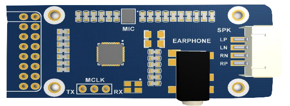
The WM8960 Audio Board, manufactured by Waveshare, is a high-performance audio codec designed for portable and multimedia applications. It features low-power stereo audio processing capabilities, supporting high-quality audio playback and recording. The board integrates advanced features such as digital signal processing (DSP), integrated amplifiers, and multiple input/output options, making it ideal for use in devices like smartphones, tablets, and other audio-centric systems.
Explore Projects Built with WM8960 Audio Board


Explore Projects Built with WM8960 Audio Board
Common Applications and Use Cases
- Portable audio devices (e.g., MP3 players, smartphones, tablets)
- Voice recording and playback systems
- Multimedia systems and IoT devices
- Audio processing in embedded systems
- Educational and prototyping projects with microcontrollers (e.g., Arduino, Raspberry Pi)
Technical Specifications
Key Technical Details
- Manufacturer: Waveshare
- Part ID: WM8960
- Audio Channels: Stereo (2-channel)
- Supported Audio Formats: 16-bit, 24-bit
- Sampling Rates: 8 kHz to 48 kHz
- Power Supply Voltage: 2.5V to 3.6V (core), 1.8V to 3.6V (I/O)
- Power Consumption: Ultra-low power for portable applications
- Integrated Features:
- Stereo DAC (Digital-to-Analog Converter) and ADC (Analog-to-Digital Converter)
- Digital Signal Processing (DSP) for audio enhancement
- Integrated headphone and speaker amplifiers
- Microphone input with biasing support
- Communication Interface: I2C (control) and I2S/PCM (audio data)
- Operating Temperature: -40°C to +85°C
Pin Configuration and Descriptions
The WM8960 Audio Board has a set of pins for power, control, and audio data communication. Below is the pin configuration:
| Pin Name | Type | Description |
|---|---|---|
| VCC | Power Input | Power supply input (3.3V recommended). |
| GND | Ground | Ground connection. |
| SCL | I2C Clock | I2C clock line for control communication. |
| SDA | I2C Data | I2C data line for control communication. |
| BCLK | Audio Clock | Bit clock for I2S/PCM audio data communication. |
| LRCLK | Audio Clock | Left/Right clock for I2S/PCM audio data communication. |
| DIN | Data Input | Audio data input for I2S/PCM communication. |
| DOUT | Data Output | Audio data output for I2S/PCM communication. |
| MIC_IN | Analog Input | Microphone input with biasing support. |
| HP_OUT_L | Analog Output | Left channel headphone output. |
| HP_OUT_R | Analog Output | Right channel headphone output. |
| SPK_OUT_L | Analog Output | Left channel speaker output. |
| SPK_OUT_R | Analog Output | Right channel speaker output. |
Usage Instructions
How to Use the WM8960 Audio Board in a Circuit
- Power Supply: Connect the VCC pin to a 3.3V power source and GND to ground. Ensure a stable power supply to avoid noise in audio signals.
- I2C Communication: Connect the SCL and SDA pins to the corresponding I2C pins of your microcontroller (e.g., Arduino or Raspberry Pi). Use pull-up resistors (typically 4.7kΩ) on the I2C lines if not already present.
- Audio Data Communication: Connect the BCLK, LRCLK, DIN, and DOUT pins to the I2S/PCM interface of your microcontroller or processor.
- Audio Input/Output:
- For microphone input, connect a microphone to the MIC_IN pin.
- For audio output, connect headphones or speakers to the HP_OUT_L/HP_OUT_R or SPK_OUT_L/SPK_OUT_R pins, respectively.
- Software Configuration: Use the I2C interface to configure the WM8960 registers for desired audio settings (e.g., sampling rate, volume, input/output selection).
Important Considerations and Best Practices
- Power Supply: Use decoupling capacitors (e.g., 0.1µF and 10µF) near the VCC pin to reduce noise and ensure stable operation.
- I2C Address: The default I2C address of the WM8960 is
0x1A. Ensure no address conflicts if multiple I2C devices are connected. - Audio Quality: Use shielded cables for audio input/output connections to minimize interference.
- Microcontroller Compatibility: Ensure your microcontroller supports I2S/PCM communication for audio data transfer.
Example: Connecting WM8960 to Arduino UNO
The Arduino UNO does not natively support I2S communication. However, you can use an external I2S module or switch to a microcontroller like the ESP32, which has built-in I2S support. Below is an example code snippet for configuring the WM8960 using I2C:
#include <Wire.h> // Include the I2C library

#define WM8960_I2C_ADDR 0x1A // Default I2C address of WM8960

void setup() {
  Wire.begin(); // Initialize I2C communication
  Serial.begin(9600); // Initialize serial communication for debugging

  // Configure WM8960 registers
  configureWM8960();
}

void loop() {
  // Main loop does nothing in this example
}

void configureWM8960() {
  // Example: Set the WM8960 to power up and enable DAC
  writeWM8960Register(0x0F, 0x000); // Reset the device
  writeWM8960Register(0x19, 0x1F0); // Enable DAC and headphone output
  writeWM8960Register(0x1A, 0x1F0); // Enable speaker output

  Serial.println("WM8960 configured successfully!");
}

void writeWM8960Register(uint8_t reg, uint16_t value) {
  Wire.beginTransmission(WM8960_I2C_ADDR);
  Wire.write((reg << 1) | ((value >> 8) & 0x01)); // Send register address
  Wire.write(value & 0xFF); // Send register value
  Wire.endTransmission();
}
Troubleshooting and FAQs
Common Issues and Solutions
No Audio Output:
- Ensure the power supply is stable and within the specified range.
- Verify that the I2C communication is working correctly by checking the connections and pull-up resistors.
- Check the audio output connections (headphones/speakers) for proper wiring.
Distorted Audio:
- Reduce the volume settings in the WM8960 configuration.
- Use shielded cables to minimize interference.
- Ensure the power supply is free from noise.
I2C Communication Failure:
- Confirm the I2C address (
0x1A) matches the device configuration. - Check for loose or incorrect connections on the SCL and SDA lines.
- Use a logic analyzer to debug I2C signals if necessary.
- Confirm the I2C address (
FAQs
Can the WM8960 work with 5V microcontrollers?
No, the WM8960 operates at 3.3V. Use a level shifter if interfacing with a 5V microcontroller.What is the maximum sampling rate supported?
The WM8960 supports sampling rates up to 48 kHz.Can I use the WM8960 with Raspberry Pi?
Yes, the WM8960 is compatible with Raspberry Pi via the I2C and I2S interfaces. Use appropriate drivers or libraries for configuration.Does the WM8960 support stereo recording?
Yes, the WM8960 supports stereo recording through its ADC and microphone input.