How to Use MFRC 522: Examples, Pinouts, and Specs
Introduction
The MFRC522 is a highly integrated RFID reader/writer IC that operates at a frequency of 13.56 MHz. It is designed for contactless communication with RFID tags and cards, making it an essential component in a wide range of applications. The MFRC522 is widely used in access control systems, payment terminals, inventory management, and other systems requiring secure and efficient data exchange.
Its compact design, low power consumption, and compatibility with microcontrollers like the Arduino UNO make it a popular choice for both hobbyists and professionals.
Explore Projects Built with MFRC 522


Explore Projects Built with MFRC 522
Technical Specifications
Below are the key technical details of the MFRC522:
- Operating Voltage: 2.5V to 3.3V (logic level), 3.3V (power supply)
- Operating Frequency: 13.56 MHz
- Communication Interface: SPI, I2C, UART (SPI is most commonly used)
- Maximum Data Rate: 424 kbit/s
- Current Consumption: 13-26 mA (active mode), 10 µA (standby mode)
- Supported Protocols: ISO/IEC 14443 A/MIFARE
- Operating Range: Up to 5 cm (depending on antenna design and tag type)
- Dimensions: 40mm x 60mm (typical breakout board)
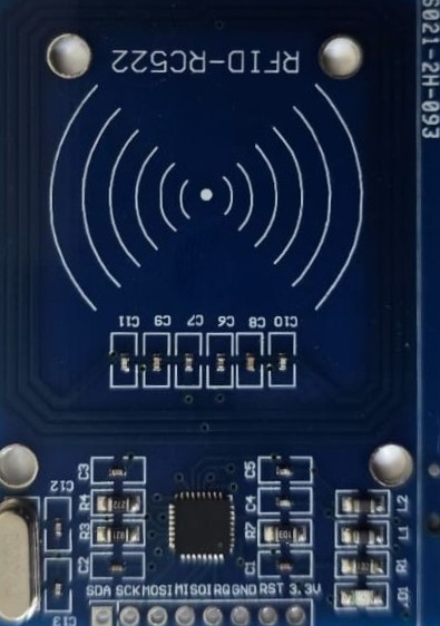
Pin Configuration and Descriptions
The MFRC522 is typically used with a breakout board that includes the IC and an antenna. Below is the pin configuration for the breakout board:
| Pin Name | Pin Number | Description |
|---|---|---|
| VCC | 1 | Power supply input (3.3V). |
| GND | 2 | Ground connection. |
| RST | 3 | Reset pin. Active LOW. Used to reset the module. |
| IRQ | 4 | Interrupt pin. Can be used to signal events (optional). |
| MISO/SCL/TX | 5 | SPI MISO (Master In Slave Out) / I2C Clock / UART TX (depending on interface). |
| MOSI/SDA/RX | 6 | SPI MOSI (Master Out Slave In) / I2C Data / UART RX (depending on interface). |
| SCK | 7 | SPI Clock. |
| NSS/SDA | 8 | SPI Chip Select (active LOW) / I2C Address Select. |
Usage Instructions
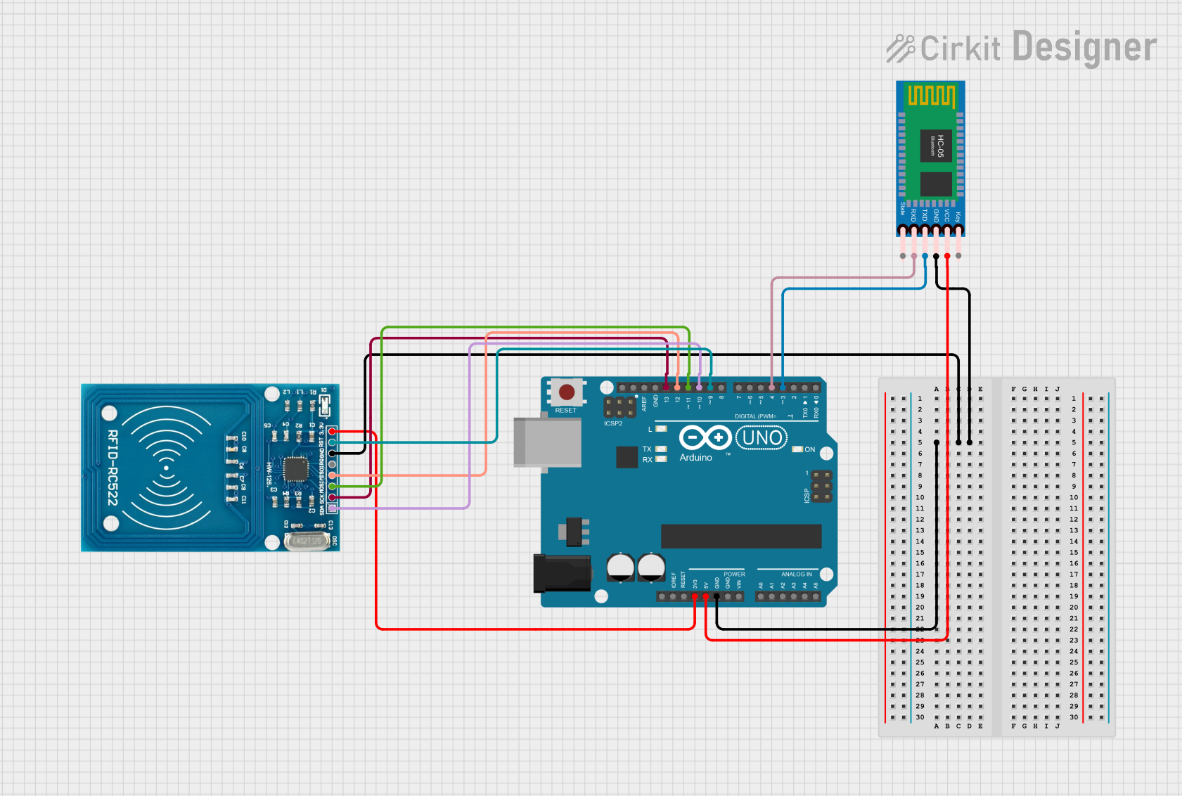
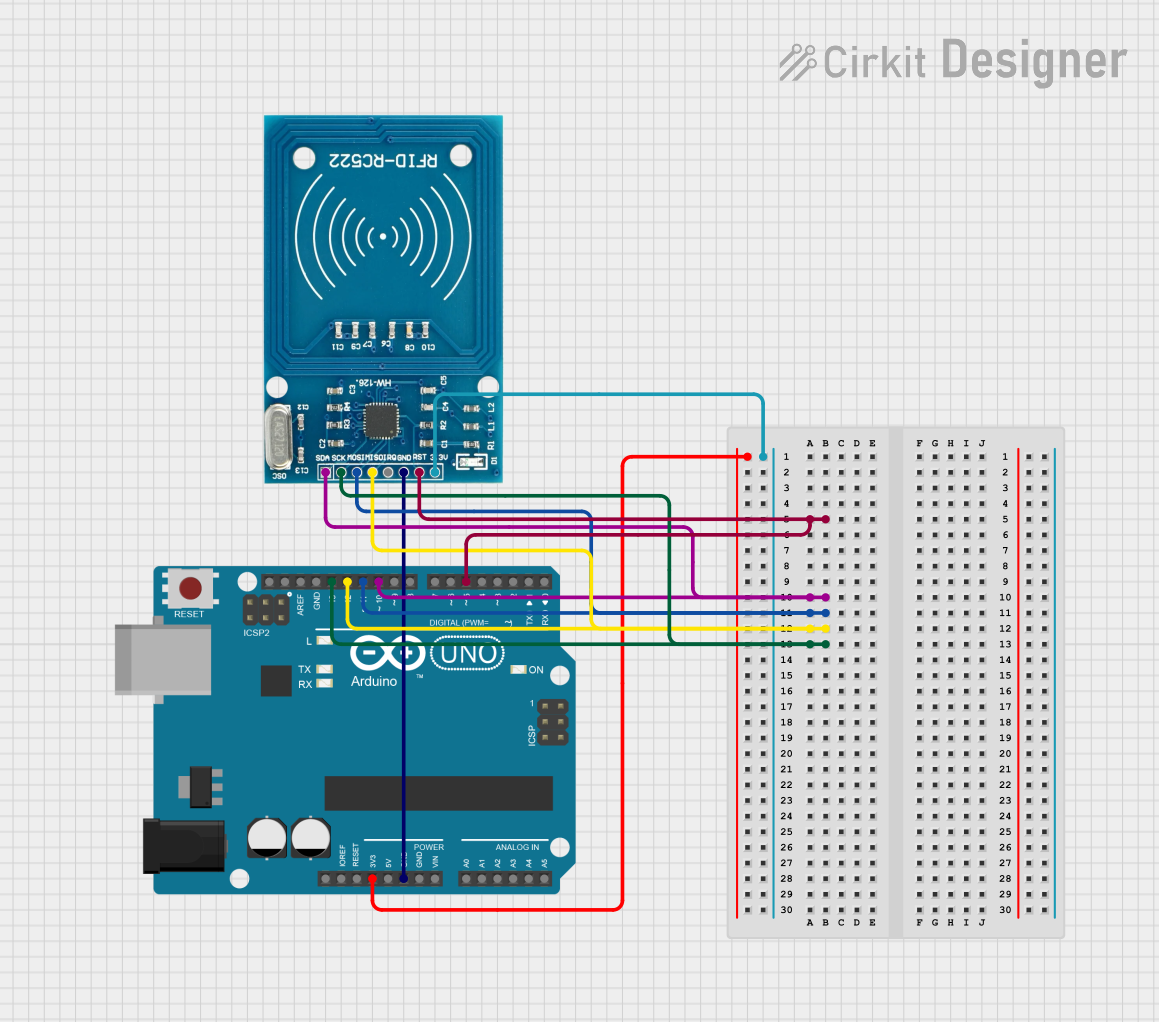
Connecting the MFRC522 to an Arduino UNO
The MFRC522 is most commonly used with the SPI interface. Below is the wiring guide for connecting the MFRC522 to an Arduino UNO:
| MFRC522 Pin | Arduino UNO Pin |
|---|---|
| VCC | 3.3V |
| GND | GND |
| RST | Pin 9 |
| IRQ | Not connected |
| MISO | Pin 12 |
| MOSI | Pin 11 |
| SCK | Pin 13 |
| NSS | Pin 10 |
Example Code for Arduino UNO
The following example demonstrates how to use the MFRC522 with an Arduino UNO to read RFID card data. This code uses the popular MFRC522 library, which can be installed via the Arduino IDE Library Manager.
#include <SPI.h>
#include <MFRC522.h>

// Define MFRC522 pins
#define RST_PIN 9  // Reset pin connected to Arduino pin 9
#define SS_PIN 10  // Slave Select pin connected to Arduino pin 10

MFRC522 rfid(SS_PIN, RST_PIN); // Create an instance of the MFRC522 class

void setup() {
  Serial.begin(9600); // Initialize serial communication
  SPI.begin();        // Initialize SPI bus
  rfid.PCD_Init();    // Initialize the MFRC522 module
  Serial.println("Place your RFID card near the reader...");
}

void loop() {
  // Check if a new card is present
  if (!rfid.PICC_IsNewCardPresent()) {
    return; // Exit if no card is detected
  }

  // Check if the card can be read
  if (!rfid.PICC_ReadCardSerial()) {
    return; // Exit if the card cannot be read
  }

  // Print the UID (Unique Identifier) of the card
  Serial.print("Card UID: ");
  for (byte i = 0; i < rfid.uid.size; i++) {
    Serial.print(rfid.uid.uidByte[i], HEX); // Print each byte in hexadecimal
    Serial.print(" ");
  }
  Serial.println();

  // Halt the card to stop communication
  rfid.PICC_HaltA();
}
Important Considerations
- Power Supply: The MFRC522 operates at 3.3V. Ensure that the VCC pin is connected to a 3.3V source. Connecting it to 5V may damage the module.
- Antenna Placement: For optimal performance, ensure that the RFID tag or card is placed flat and close to the antenna.
- Library Installation: Install the
MFRC522library from the Arduino IDE Library Manager before uploading the code. - SPI Configuration: Ensure that the SPI pins on the Arduino UNO are correctly connected to the MFRC522 module.
Troubleshooting and FAQs
Common Issues
The module is not detected by the Arduino.
- Solution: Double-check the wiring, especially the SPI connections (MISO, MOSI, SCK, and NSS).
- Ensure that the
SS_PINandRST_PINin the code match your wiring.
The RFID card is not being read.
- Solution: Ensure that the card is compatible with the MFRC522 (e.g., MIFARE cards).
- Place the card closer to the antenna and ensure there are no obstructions.
The module is overheating.
- Solution: Verify that the VCC pin is connected to a 3.3V source, not 5V.
The UID is not displayed correctly.
- Solution: Check the serial monitor baud rate (set to 9600 in the example code).
- Ensure that the RFID card is properly aligned with the antenna.
FAQs
Can the MFRC522 read NFC tags?
- Yes, the MFRC522 supports ISO/IEC 14443 A, which is compatible with many NFC tags.
What is the maximum range of the MFRC522?
- The typical range is up to 5 cm, depending on the antenna design and the type of RFID tag.
Can I use the MFRC522 with a 5V microcontroller?
- Yes, but you must use level shifters for the SPI pins to avoid damaging the module.
Is it possible to write data to RFID cards using the MFRC522?
- Yes, the MFRC522 supports both reading and writing operations for compatible RFID cards.
By following this documentation, you can successfully integrate the MFRC522 into your projects and troubleshoot common issues effectively.