Cirkit Designer Logo
Cirkit Designer
Your all-in-one circuit design IDE
Home / 
Component Documentation

How to Use VL53L0X: Examples, Pinouts, and Specs

Image of VL53L0X
Cirkit Designer LogoDesign with VL53L0X in Cirkit Designer

Introduction

The VL53L0X is a compact and high-performance time-of-flight (ToF) distance sensor manufactured by STMicroelectronics. It uses laser technology to measure distances with high accuracy and speed, making it ideal for applications requiring precise distance measurements. The sensor can measure distances up to 2 meters and is designed to work in a variety of lighting conditions.

Explore Projects Built with VL53L0X

Use Cirkit Designer to design, explore, and prototype these projects online. Some projects support real-time simulation. Click "Open Project" to start designing instantly!
Arduino UNO with A9G GSM/GPRS and Dual VL53L1X Distance Sensors
Image of TED CIRCUIT : A project utilizing VL53L0X in a practical application
This circuit features an Arduino UNO microcontroller interfaced with an A9G GSM/GPRS+GPS/BDS module and two VL53L1X time-of-flight distance sensors. The A9G module is connected to the Arduino via serial communication for GPS and GSM functionalities, while both VL53L1X sensors are connected through I2C with shared SDA and SCL lines and individual SHUT pins for selective sensor activation. The Arduino is programmed to control these peripherals, although the specific functionality is not detailed in the provided code.
Cirkit Designer LogoOpen Project in Cirkit Designer
Arduino UNO R4 WiFi Laser Module with Distance Sensor
Image of KIT 1: SENSOR KIT: A project utilizing VL53L0X in a practical application
This circuit features an Arduino UNO R4 WiFi connected to a VL53L0X distance sensor via I2C for distance measurement. Additionally, a tube laser module is powered by a battery case and controlled through a rocker switch, with a terminal block connector completing the circuit.
Cirkit Designer LogoOpen Project in Cirkit Designer
ESP8266 NodeMCU-Based Smart Eye Pressure Monitor with OLED Display and Wi-Fi Connectivity
Image of Copy of test 2 (7): A project utilizing VL53L0X in a practical application
This circuit features an ESP8266 NodeMCU microcontroller interfaced with a VL53L0X time-of-flight distance sensor, a 0.96" OLED display, a piezo sensor, and a photodiode for light detection. The ESP8266 collects data from the sensors, displays readings on the OLED, and hosts a web server to present the information. It is likely designed for distance measurement, light intensity detection, and pressure sensing, with the capability to monitor and display these parameters in real-time over WiFi.
Cirkit Designer LogoOpen Project in Cirkit Designer
Arduino Mega 2560-Based Multi-Sensor System with Distance, Magnetometer, and Camera Integration
Image of Junior Design - Sensors: A project utilizing VL53L0X in a practical application
This circuit features an Arduino Mega 2560 microcontroller interfaced with multiple VL53L0X distance sensors, an OV7725 camera module, and an Adafruit LIS3MDL triple-axis magnetometer. The Arduino reads data from these sensors and the camera, likely for a robotics or environmental sensing application, and processes the data for further use or transmission.
Cirkit Designer LogoOpen Project in Cirkit Designer

Explore Projects Built with VL53L0X

Use Cirkit Designer to design, explore, and prototype these projects online. Some projects support real-time simulation. Click "Open Project" to start designing instantly!
Image of TED CIRCUIT : A project utilizing VL53L0X in a practical application
Arduino UNO with A9G GSM/GPRS and Dual VL53L1X Distance Sensors
This circuit features an Arduino UNO microcontroller interfaced with an A9G GSM/GPRS+GPS/BDS module and two VL53L1X time-of-flight distance sensors. The A9G module is connected to the Arduino via serial communication for GPS and GSM functionalities, while both VL53L1X sensors are connected through I2C with shared SDA and SCL lines and individual SHUT pins for selective sensor activation. The Arduino is programmed to control these peripherals, although the specific functionality is not detailed in the provided code.
Cirkit Designer LogoOpen Project in Cirkit Designer
Image of KIT 1: SENSOR KIT: A project utilizing VL53L0X in a practical application
Arduino UNO R4 WiFi Laser Module with Distance Sensor
This circuit features an Arduino UNO R4 WiFi connected to a VL53L0X distance sensor via I2C for distance measurement. Additionally, a tube laser module is powered by a battery case and controlled through a rocker switch, with a terminal block connector completing the circuit.
Cirkit Designer LogoOpen Project in Cirkit Designer
Image of Copy of test 2 (7): A project utilizing VL53L0X in a practical application
ESP8266 NodeMCU-Based Smart Eye Pressure Monitor with OLED Display and Wi-Fi Connectivity
This circuit features an ESP8266 NodeMCU microcontroller interfaced with a VL53L0X time-of-flight distance sensor, a 0.96" OLED display, a piezo sensor, and a photodiode for light detection. The ESP8266 collects data from the sensors, displays readings on the OLED, and hosts a web server to present the information. It is likely designed for distance measurement, light intensity detection, and pressure sensing, with the capability to monitor and display these parameters in real-time over WiFi.
Cirkit Designer LogoOpen Project in Cirkit Designer
Image of Junior Design - Sensors: A project utilizing VL53L0X in a practical application
Arduino Mega 2560-Based Multi-Sensor System with Distance, Magnetometer, and Camera Integration
This circuit features an Arduino Mega 2560 microcontroller interfaced with multiple VL53L0X distance sensors, an OV7725 camera module, and an Adafruit LIS3MDL triple-axis magnetometer. The Arduino reads data from these sensors and the camera, likely for a robotics or environmental sensing application, and processes the data for further use or transmission.
Cirkit Designer LogoOpen Project in Cirkit Designer

Common Applications

  • Robotics and automation
  • Obstacle detection and avoidance
  • Gesture recognition
  • Proximity sensing
  • Industrial and consumer electronics

Technical Specifications

The following table outlines the key technical details of the VL53L0X sensor:

Parameter Value
Operating Voltage 2.6V to 3.5V
Communication Interface I²C
Measurement Range 30mm to 2000mm (2 meters)
Measurement Accuracy ±3% (typical)
Field of View (FoV) 25°
Operating Temperature Range -20°C to +70°C
Power Consumption (Active) ~20mW
Dimensions 4.4mm x 2.4mm x 1.0mm

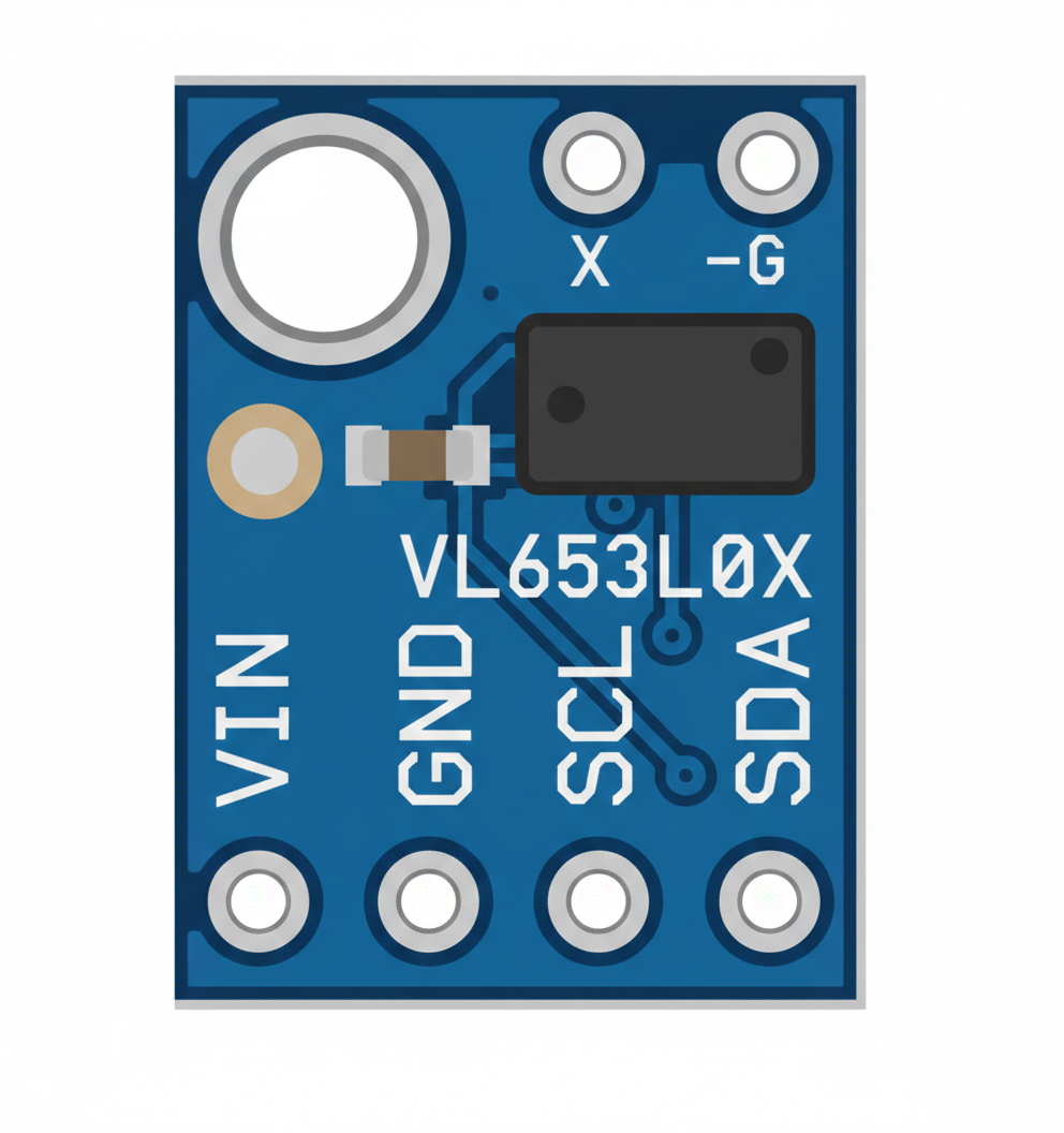
Pin Configuration and Descriptions

The VL53L0X sensor has the following pinout:

Pin Name Pin Number Description
VIN 1 Power supply input (2.6V to 3.5V)
GND 2 Ground
SDA 3 I²C data line
SCL 4 I²C clock line
XSHUT 5 Shutdown pin (active low, used to reset the sensor)
GPIO1 6 Interrupt output (optional, configurable)

Usage Instructions

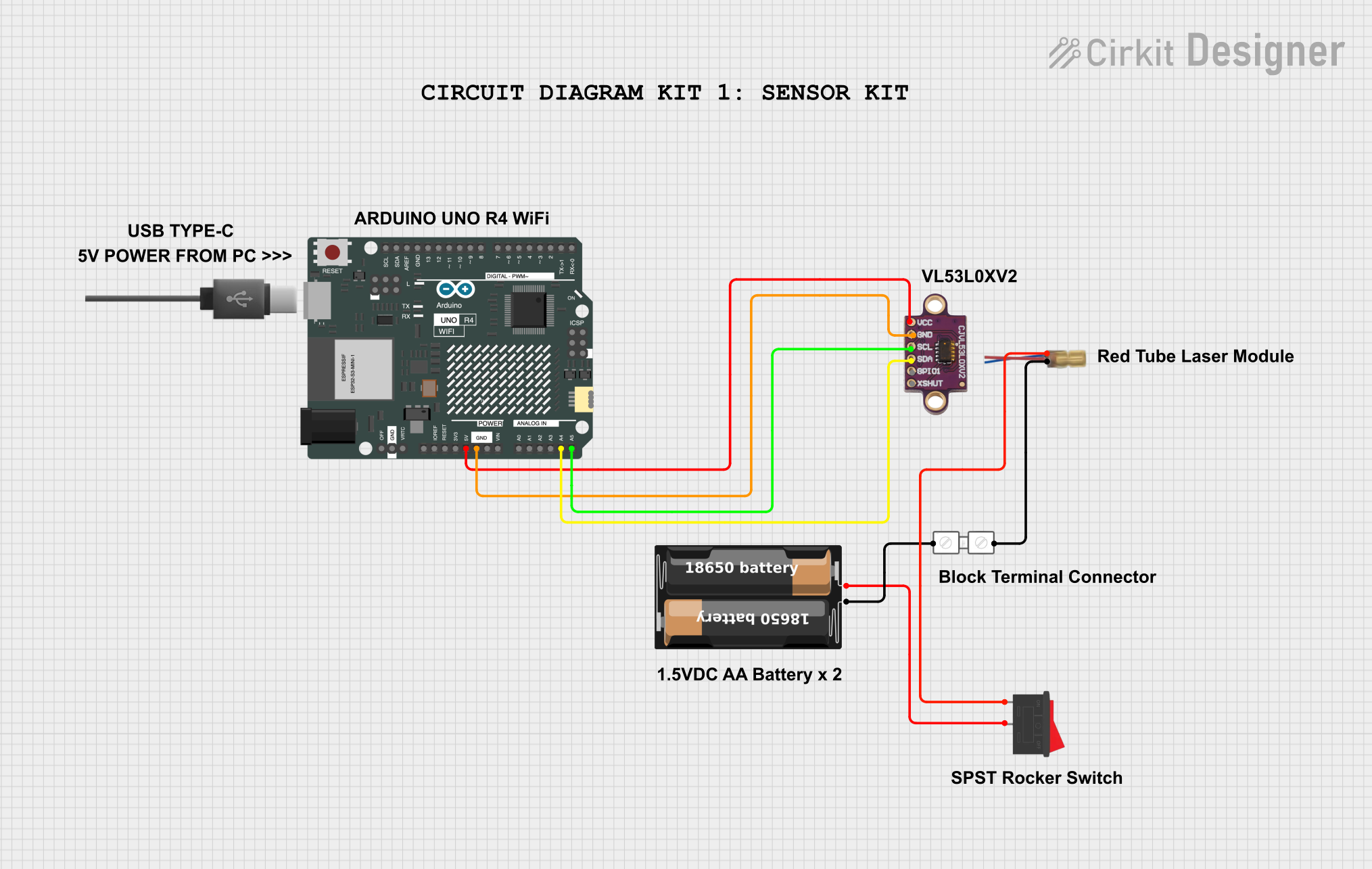
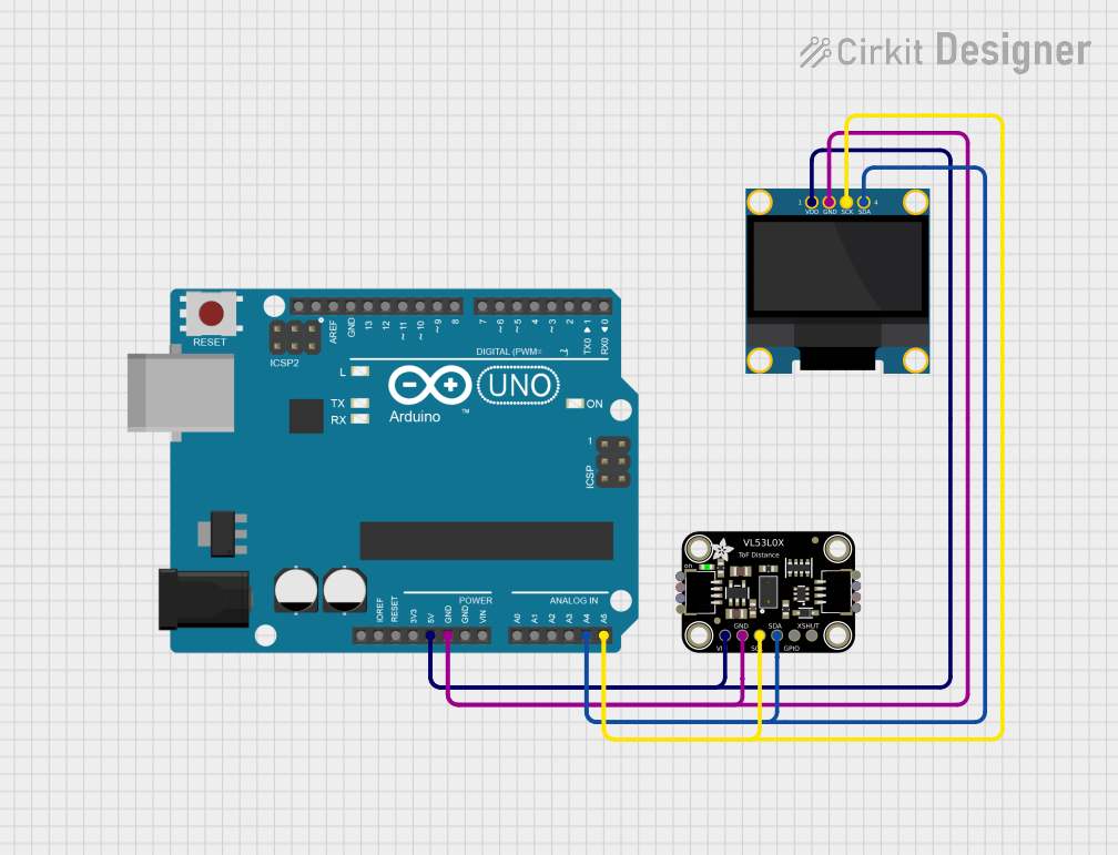
How to Use the VL53L0X in a Circuit

  1. Power Supply: Connect the VIN pin to a 3.3V power source and the GND pin to ground.
  2. I²C Communication: Connect the SDA and SCL pins to the corresponding I²C pins on your microcontroller. Use pull-up resistors (typically 4.7kΩ) on both lines if not already present.
  3. Shutdown Control: Optionally, connect the XSHUT pin to a GPIO pin on your microcontroller to enable or disable the sensor.
  4. Interrupt Pin: The GPIO1 pin can be used for interrupt-driven applications but is not mandatory for basic operation.

Important Considerations

  • I²C Address: The default I²C address of the VL53L0X is 0x29. Ensure no other devices on the I²C bus share this address.
  • Ambient Light: The sensor is designed to work in various lighting conditions, but excessive ambient light may slightly affect accuracy.
  • Distance Limitations: The sensor performs best within its specified range (30mm to 2000mm). Measurements outside this range may be unreliable.

Example Code for Arduino UNO

Below is an example of how to interface the VL53L0X with an Arduino UNO using the Adafruit VL53L0X library:

#include <Wire.h>
#include <Adafruit_VL53L0X.h>

// Create an instance of the VL53L0X sensor
Adafruit_VL53L0X lox = Adafruit_VL53L0X();

void setup() {
  Serial.begin(9600); // Initialize serial communication
  while (!Serial) {
    delay(10); // Wait for the serial port to be ready
  }

  Serial.println("VL53L0X Test");

  // Initialize the sensor
  if (!lox.begin()) {
    Serial.println("Failed to find VL53L0X sensor!");
    while (1) {
      delay(10); // Halt execution if the sensor is not found
    }
  }
}

void loop() {
  VL53L0X_RangingMeasurementData_t measure;

  // Perform a distance measurement
  lox.rangingTest(&measure, false);

  // Check if the measurement is valid
  if (measure.RangeStatus != 4) { // 4 indicates an out-of-range error
    Serial.print("Distance (mm): ");
    Serial.println(measure.RangeMilliMeter);
  } else {
    Serial.println("Out of range");
  }

  delay(100); // Wait before the next measurement
}

Best Practices

  • Use decoupling capacitors (e.g., 0.1µF) near the VIN pin to stabilize the power supply.
  • Keep the sensor's optical path clear of obstructions for accurate measurements.
  • Avoid placing the sensor too close to highly reflective surfaces, as this may cause measurement errors.

Troubleshooting and FAQs

Common Issues and Solutions

  1. Sensor Not Detected on I²C Bus

    • Ensure the sensor is powered correctly (VIN and GND connected).
    • Verify the I²C connections (SDA and SCL) and check for proper pull-up resistors.
    • Confirm the I²C address (0x29) is not conflicting with other devices.
  2. Inaccurate Distance Measurements

    • Ensure the sensor is within its specified range (30mm to 2000mm).
    • Check for obstructions or reflective surfaces in the sensor's field of view.
    • Minimize ambient light interference by shielding the sensor if necessary.
  3. Sensor Not Responding After Power-Up

    • Toggle the XSHUT pin to reset the sensor.
    • Verify the power supply voltage is within the specified range (2.6V to 3.5V).

FAQs

Q: Can the VL53L0X measure distances beyond 2 meters?
A: No, the sensor is designed for a maximum range of 2 meters. Measurements beyond this range may be unreliable.

Q: Is the VL53L0X suitable for outdoor use?
A: While the sensor can operate in various lighting conditions, it is not weatherproof and should be protected from moisture and extreme temperatures.

Q: Can multiple VL53L0X sensors be used on the same I²C bus?
A: Yes, but each sensor must have a unique I²C address. This can be achieved by toggling the XSHUT pin and reprogramming the address for each sensor.

Q: What is the typical response time for a distance measurement?
A: The sensor can perform measurements in as little as 30ms, depending on the configuration.

By following this documentation, users can effectively integrate the VL53L0X into their projects and troubleshoot common issues.