
How to Use Basic FET P-Channel: Examples, Pinouts, and Specs
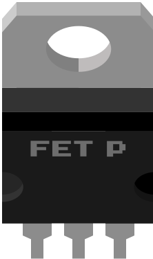
 Design with Basic FET P-Channel in Cirkit Designer
Introduction
The Basic FET P-Channel is a type of Field Effect Transistor (FET) that enables current to flow from the source to the drain when a negative voltage is applied to the gate terminal. This component is widely used in electronic circuits for switching and signal amplification purposes. Its ability to handle high-speed switching and low power consumption makes it a versatile choice for various applications.
Explore Projects Built with Basic FET P-Channel
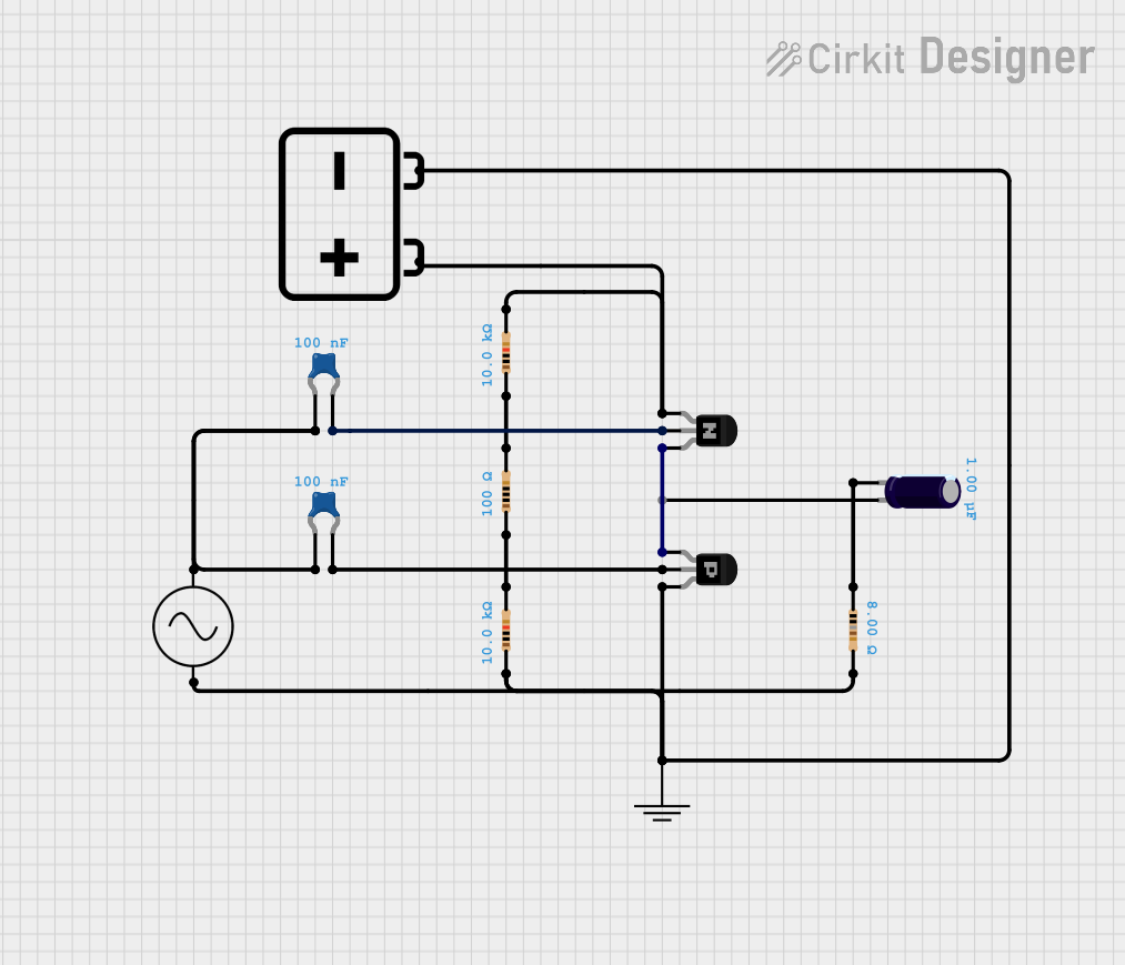 Open Project in Cirkit Designer
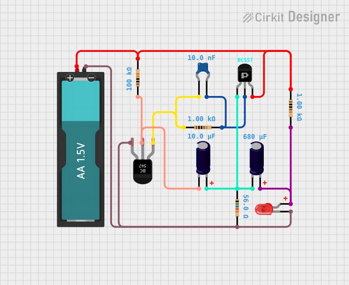 Open Project in Cirkit Designer
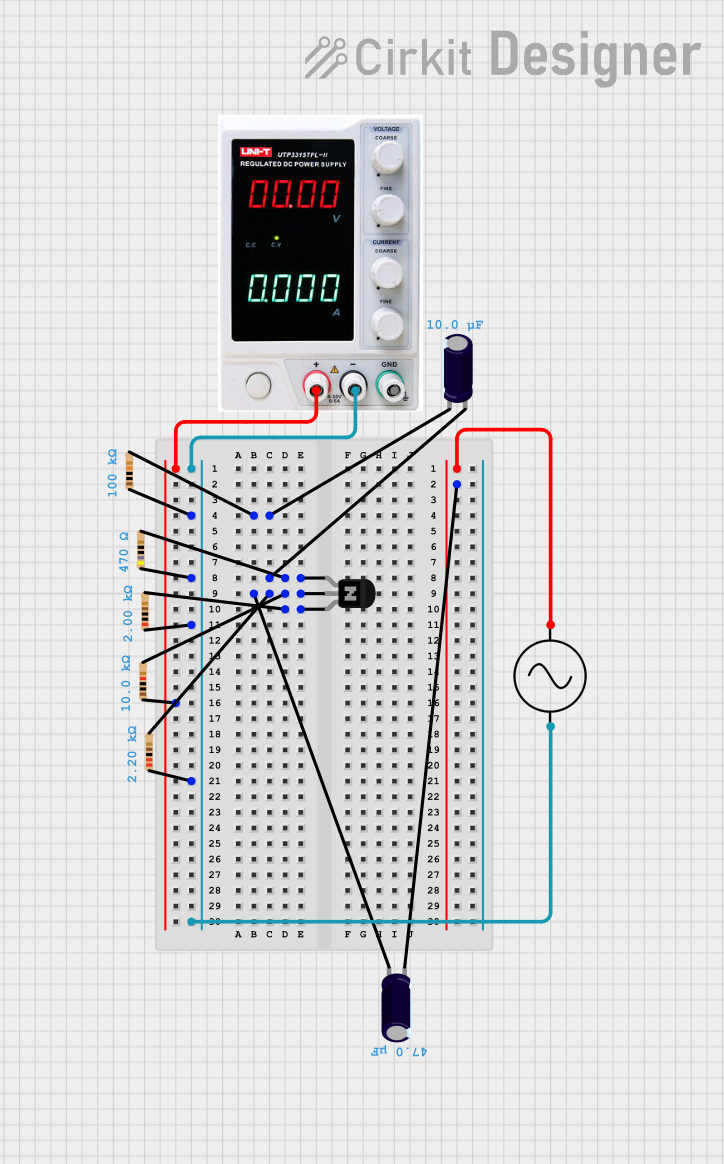 Open Project in Cirkit Designer
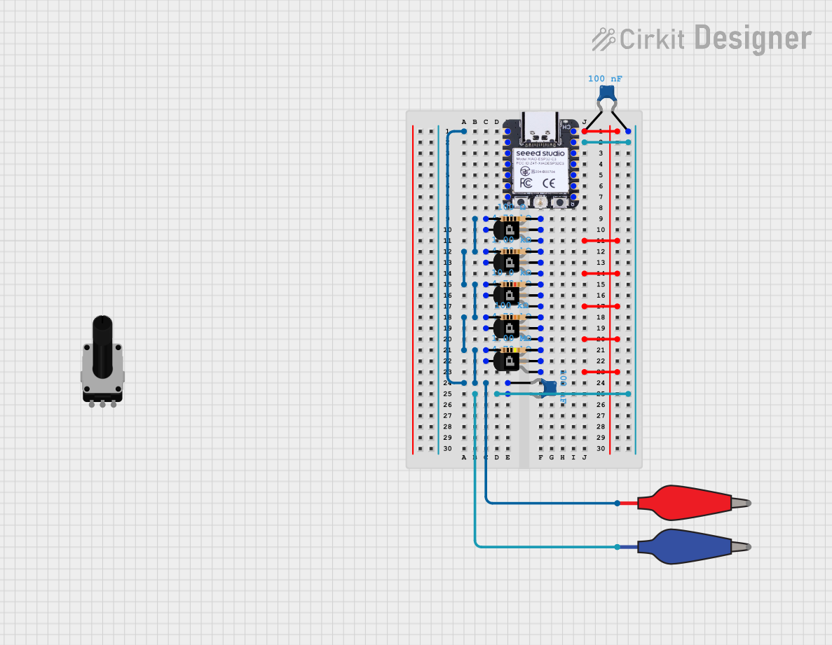 Open Project in Cirkit Designer
Explore Projects Built with Basic FET P-Channel
Open Project in Cirkit DesignerOpen Project in Cirkit DesignerOpen Project in Cirkit DesignerOpen Project in Cirkit DesignerCommon Applications
- Power management circuits
- Load switching in low-side or high-side configurations
- Signal amplification in analog circuits
- Motor control and LED dimming
- Battery protection circuits
Technical Specifications
Below are the key technical details of the Basic FET P-Channel:
| Parameter | Value |
|---|---|
| Type | P-Channel MOSFET |
| Maximum Drain-Source Voltage (VDS) | -30V |
| Maximum Gate-Source Voltage (VGS) | ±20V |
| Continuous Drain Current (ID) | -2A |
| Power Dissipation (PD) | 1W |
| Threshold Voltage (VGS(th)) | -1V to -3V |
| RDS(on) (On-Resistance) | 0.1Ω |
| Operating Temperature Range | -55°C to +150°C |
| Package Type | TO-220, SOT-23, or similar |
Pin Configuration
The Basic FET P-Channel typically has three pins. Below is the pinout description:
| Pin Number | Pin Name | Description |
|---|---|---|
| 1 | Gate | Controls the flow of current between the source and drain. |
| 2 | Source | The terminal where current enters the FET. |
| 3 | Drain | The terminal where current exits the FET. |
Usage Instructions
How to Use the Basic FET P-Channel in a Circuit
- Connect the Source Terminal: Attach the source terminal to the positive voltage supply.
- Connect the Drain Terminal: Connect the drain terminal to the load (e.g., motor, LED, or other components).
- Control the Gate Voltage: Apply a negative voltage to the gate terminal relative to the source to turn the FET on. When the gate voltage is 0V or positive relative to the source, the FET will remain off.
- Use a Gate Resistor: To limit the inrush current to the gate, use a resistor (typically 10kΩ) between the gate and the control signal.
Important Considerations
- Voltage Ratings: Ensure that the applied voltages do not exceed the maximum VDS or VGS ratings to avoid damaging the FET.
- Heat Dissipation: If the FET operates at high currents, consider using a heatsink to manage heat dissipation.
- Gate Drive Voltage: Ensure the control circuit can provide sufficient negative voltage to fully turn on the FET.
- Protection Diodes: Add a flyback diode across inductive loads (e.g., motors) to protect the FET from voltage spikes.
Example: Using the Basic FET P-Channel with Arduino UNO
Below is an example of how to use the Basic FET P-Channel to control an LED with an Arduino UNO:
// Define the pin connected to the FET gate
const int gatePin = 9;

void setup() {
  pinMode(gatePin, OUTPUT); // Set the gate pin as an output
}

void loop() {
  digitalWrite(gatePin, LOW); // Turn the FET on (negative voltage at gate)
  delay(1000);               // Keep the LED on for 1 second
  digitalWrite(gatePin, HIGH); // Turn the FET off (0V at gate)
  delay(1000);               // Keep the LED off for 1 second
}
Note: In this example, the source terminal of the FET is connected to the positive voltage supply, and the drain terminal is connected to the LED and its current-limiting resistor. The gate is controlled by the Arduino UNO.
Troubleshooting and FAQs
Common Issues
FET Not Turning On
- Cause: Insufficient negative gate voltage.
- Solution: Verify that the gate voltage is sufficiently negative relative to the source (e.g., -5V or lower).
Excessive Heat
- Cause: High current through the FET or insufficient heat dissipation.
- Solution: Use a heatsink or ensure the FET operates within its rated current and power limits.
Load Not Operating
- Cause: Incorrect wiring or damaged FET.
- Solution: Double-check the circuit connections and replace the FET if necessary.
Voltage Spikes Damaging the FET
- Cause: Inductive loads generating back EMF.
- Solution: Add a flyback diode across the load to suppress voltage spikes.
FAQs
Q1: Can I use the Basic FET P-Channel for high-frequency switching?
A1: Yes, P-Channel FETs are suitable for high-frequency switching, but ensure the gate drive circuit can handle the required switching speed.
Q2: What happens if I apply a positive voltage to the gate?
A2: Applying a positive voltage to the gate will turn the FET off, preventing current flow between the source and drain.
Q3: Can I use this FET for low-voltage applications?
A3: Yes, the Basic FET P-Channel can operate at low voltages, but ensure the gate voltage is sufficiently negative to fully turn it on.
Q4: How do I calculate the required gate resistor value?
A4: A typical value is 10kΩ, but you can calculate it based on the gate capacitance and desired switching speed. Lower resistance values allow faster switching but increase current draw.
By following this documentation, you can effectively integrate the Basic FET P-Channel into your electronic projects!