
How to Use Power Distribution Board (PDB) 60A: Examples, Pinouts, and Specs
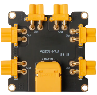
 Design with Power Distribution Board (PDB) 60A in Cirkit Designer
Introduction
The Holybro Power Distribution Board (PDB) 60A is a robust and efficient circuit board designed to distribute electrical power to multiple components in a system. With a maximum current handling capacity of 60 amps, this PDB is ideal for high-power applications such as drones, RC vehicles, and robotics. It simplifies power management by providing multiple output terminals, ensuring reliable and safe power delivery to connected devices.
Explore Projects Built with Power Distribution Board (PDB) 60A
 Open Project in Cirkit Designer
 Open Project in Cirkit Designer
 Open Project in Cirkit Designer
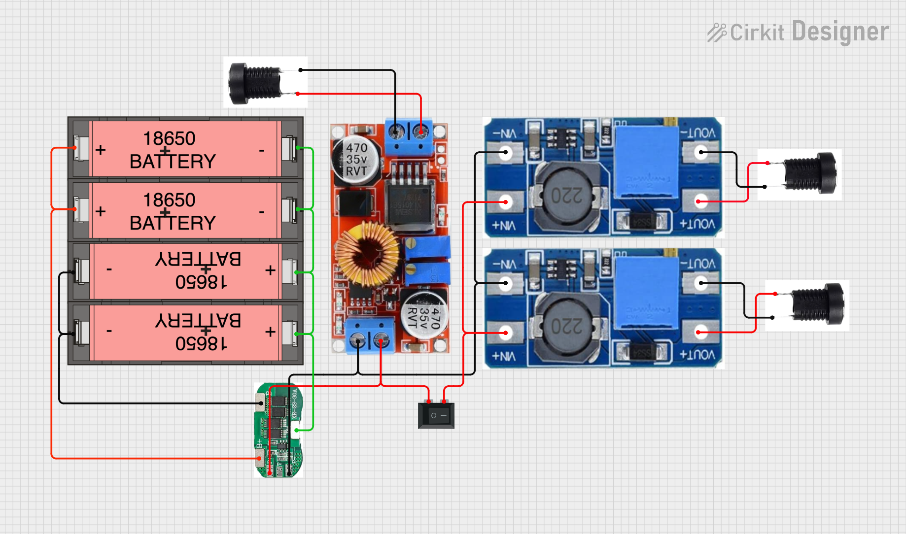 Open Project in Cirkit Designer
Explore Projects Built with Power Distribution Board (PDB) 60A
Open Project in Cirkit DesignerOpen Project in Cirkit DesignerOpen Project in Cirkit DesignerOpen Project in Cirkit DesignerCommon Applications
- Multirotor drones (e.g., quadcopters, hexacopters)
- RC vehicles (cars, boats, planes)
- Robotics and automation systems
- High-power LED lighting systems
- Custom electronics projects requiring centralized power distribution
Technical Specifications
The Holybro PDB 60A is designed to meet the demands of high-current applications while maintaining a compact and lightweight form factor. Below are the key technical details:
General Specifications
| Parameter | Value |
|---|---|
| Maximum Current | 60A |
| Input Voltage Range | 2S-6S LiPo (7.4V - 22.2V) |
| Dimensions | 36mm x 50mm |
| Weight | 10g |
| PCB Material | 4-layer PCB with copper traces |
| Operating Temperature | -20°C to 85°C |
Pin Configuration and Descriptions
The PDB features multiple input and output terminals for efficient power distribution. Below is the pin configuration:
Input Terminals
| Pin Name | Description |
|---|---|
| VIN+ | Positive input terminal (connect to battery positive) |
| VIN- | Negative input terminal (connect to battery negative) |
Output Terminals
| Pin Name | Description |
|---|---|
| VOUT+ | Positive output terminal for devices |
| VOUT- | Negative output terminal for devices |
| ESC Pads | Dedicated pads for connecting ESCs (Electronic Speed Controllers) |
Additional Features
- BEC (Battery Eliminator Circuit): Provides regulated 5V and/or 12V outputs for powering flight controllers or other low-power devices.
- Current Sensor Pads: Optional pads for connecting a current sensor to monitor power usage.
Usage Instructions
How to Use the PDB in a Circuit
- Connect the Battery:
- Solder the battery's positive wire to the VIN+ terminal.
- Solder the battery's negative wire to the VIN- terminal.
- Connect the Devices:
- Solder the positive and negative wires of each device (e.g., ESCs, flight controllers, LEDs) to the corresponding VOUT+ and VOUT- terminals.
- For ESCs, use the dedicated ESC pads for a secure connection.
- Optional Connections:
- If your PDB includes a BEC, connect the regulated output to your flight controller or other low-power devices.
- Use the current sensor pads if you need to monitor power consumption.
Important Considerations
- Soldering Tips:
- Use a high-quality soldering iron and lead-free solder for reliable connections.
- Avoid overheating the PCB to prevent damage to the copper traces.
- Power Ratings:
- Ensure that the total current drawn by all connected devices does not exceed 60A.
- Use appropriately rated wires and connectors to handle high currents.
- Mounting:
- Secure the PDB to your frame or chassis using non-conductive spacers to prevent short circuits.
- Safety:
- Double-check all connections before powering on the system.
- Use a fuse or circuit breaker for additional protection.
Example: Connecting to an Arduino UNO
If you are using the PDB to power an Arduino UNO, follow these steps:
- Connect the PDB's 5V BEC output to the Arduino's 5V pin.
- Connect the PDB's ground (GND) to the Arduino's GND pin.
Here is a simple Arduino code example to read voltage from a sensor connected to the PDB:
// Define the analog pin connected to the voltage sensor
const int voltagePin = A0;

// Variable to store the voltage reading
float voltage = 0.0;

void setup() {
  // Initialize serial communication for debugging
  Serial.begin(9600);
}

void loop() {
  // Read the analog value from the voltage sensor
  int sensorValue = analogRead(voltagePin);

  // Convert the analog value to voltage (assuming a 5V reference)
  voltage = sensorValue * (5.0 / 1023.0);

  // Print the voltage to the Serial Monitor
  Serial.print("Voltage: ");
  Serial.print(voltage);
  Serial.println(" V");

  // Wait for 1 second before the next reading
  delay(1000);
}
Troubleshooting and FAQs
Common Issues
- No Power Output:
- Cause: Poor soldering or loose connections.
- Solution: Inspect and re-solder all connections. Ensure wires are securely attached to the terminals.
- Overheating:
- Cause: Exceeding the 60A current limit or using undersized wires.
- Solution: Reduce the load or use thicker wires to handle high currents.
- Short Circuit:
- Cause: Improper mounting or exposed wires touching the PCB.
- Solution: Use non-conductive spacers and insulate exposed wires.
FAQs
Q: Can I use this PDB with a 4S LiPo battery?
A: Yes, the PDB supports 2S-6S LiPo batteries, so a 4S battery (14.8V) is compatible.
Q: Does the PDB include a built-in current sensor?
A: Some versions of the Holybro PDB 60A include optional pads for connecting an external current sensor, but it does not have a built-in sensor.
Q: Can I power multiple ESCs from this PDB?
A: Yes, the PDB is designed to handle multiple ESCs, provided the total current does not exceed 60A.
Q: Is the PDB waterproof?
A: No, the PDB is not waterproof. Use conformal coating or other protective measures if operating in wet conditions.
By following this documentation, you can effectively integrate the Holybro Power Distribution Board (PDB) 60A into your project for efficient and reliable power distribution.