How to Use Adafruit Stereo 2.1W Class D Audio Amplifier - TPA2012: Examples, Pinouts, and Specs
Introduction
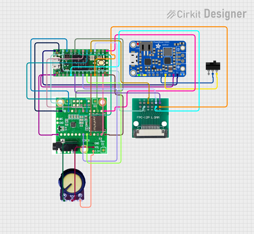
The Adafruit Stereo 2.1W Class D Audio Amplifier - TPA2012 is a small, powerful, and efficient module designed to amplify audio signals for stereo output. Utilizing the TPA2012 integrated circuit, this amplifier is capable of delivering high-quality sound with minimal power loss, making it ideal for portable and battery-powered applications. Common applications include DIY audio projects, portable speakers, and any application requiring amplified stereo sound.
Explore Projects Built with Adafruit Stereo 2.1W Class D Audio Amplifier - TPA2012
Explore Projects Built with Adafruit Stereo 2.1W Class D Audio Amplifier - TPA2012
Technical Specifications
Key Technical Details
- Type: Class D
- Output Power: 2.1W per channel at 4Ω, 10% THD; 1.4W per channel at 8Ω, 10% THD
- Supply Voltage: 2.7V to 5.5V DC
- Quiescent Current: 6mA (typical)
- Efficiency: Up to 90%
- Signal-to-Noise Ratio (SNR): 90dB (typical)
- Total Harmonic Distortion + Noise (THD+N): 0.1% (typical)
- Gain: Fixed 24dB gain
- Speaker Impedance: 4Ω to 8Ω
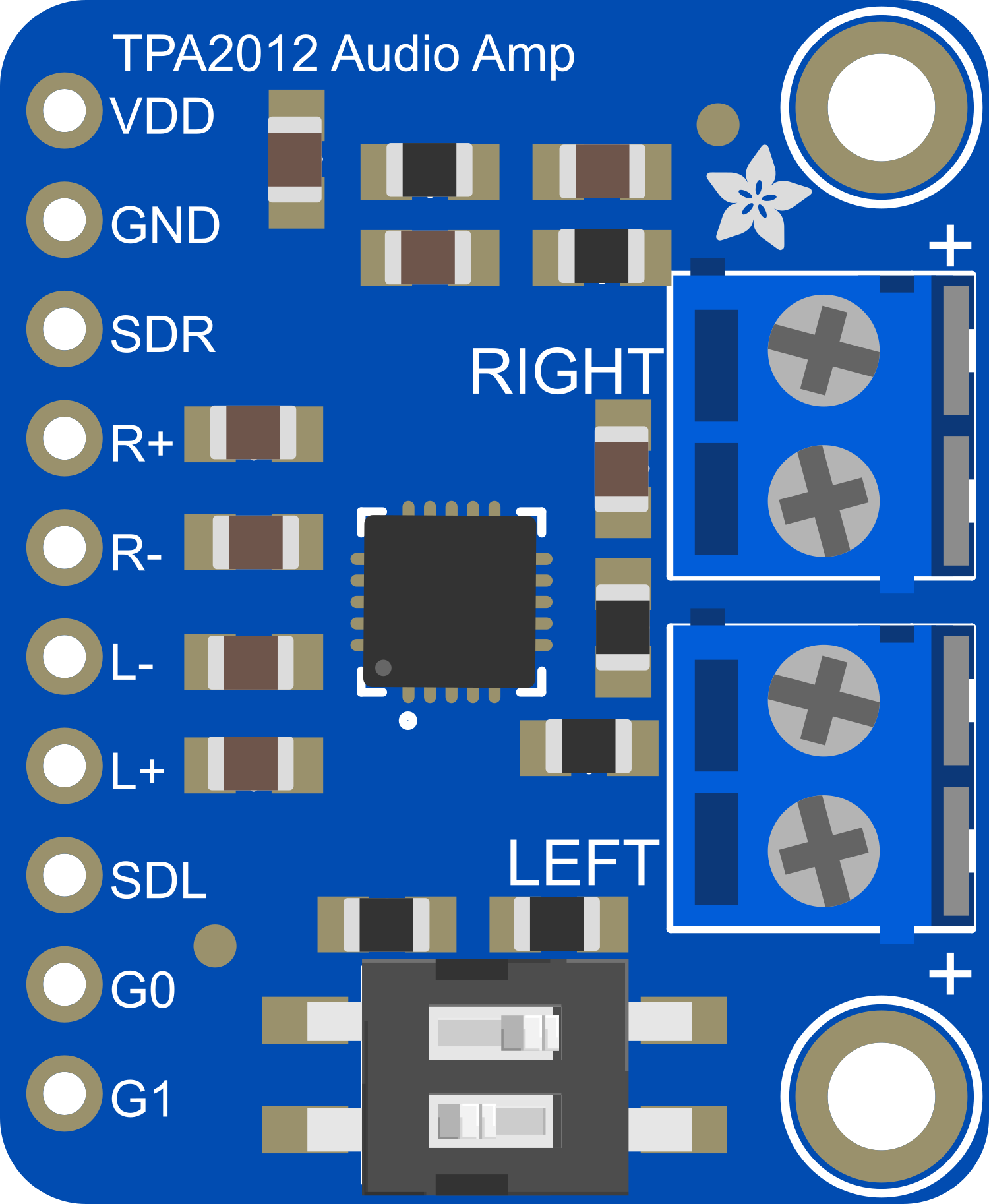
Pin Configuration and Descriptions
| Pin Number | Name | Description |
|---|---|---|
| 1 | VIN | Supply voltage (2.7V to 5.5V DC) |
| 2 | GND | Ground connection |
| 3 | A+ | Positive input for left channel |
| 4 | A- | Negative input for left channel (ground for single-ended input) |
| 5 | B+ | Positive input for right channel |
| 6 | B- | Negative input for right channel (ground for single-ended input) |
| 7 | L+ | Positive output for left channel speaker |
| 8 | L- | Negative output for left channel speaker |
| 9 | R+ | Positive output for right channel speaker |
| 10 | R- | Negative output for right channel speaker |
| 11 | SD | Shutdown pin (active low) |
| 12 | GAIN | Gain selection (leave floating for 24dB gain) |
Usage Instructions
How to Use the Component in a Circuit
- Power Supply: Connect the VIN pin to a 2.7V to 5.5V DC power supply and the GND pin to the ground of your power source.
- Audio Input: Connect your audio source to the A+ and A- pins for the left channel and the B+ and B- pins for the right channel. For single-ended input signals, connect A- and B- to ground.
- Speaker Output: Connect your speakers to the L+ and L- pins for the left channel and the R+ and R- pins for the right channel.
- Shutdown Control: To enable the amplifier, ensure the SD pin is pulled high. To put the amplifier in shutdown mode, pull the SD pin low.
- Gain Setting: The gain is fixed at 24dB. If adjustable gain is required, additional circuitry is needed.
Important Considerations and Best Practices
- Ensure that the power supply does not exceed 5.5V to prevent damage to the amplifier.
- Use capacitors at the power supply lines close to the amplifier to filter out noise and provide a stable voltage.
- Avoid long wires for the speaker connections to minimize potential signal loss or interference.
- Ensure that the speakers used are within the supported impedance range (4Ω to 8Ω).
- To prevent unwanted noise, keep audio input lines as short as possible and away from sources of electrical noise.
Troubleshooting and FAQs
Common Issues
- No Sound Output: Check power supply connections, ensure that the SD pin is high, and verify that the audio input is connected correctly.
- Distorted Sound: Ensure that the input signal level is not too high, causing clipping. Also, check that the speakers are functioning correctly and are within the specified impedance range.
- Unexpected Noise: Use shielded cables for audio inputs and keep them away from power lines or other sources of interference.
FAQs
Q: Can I use this amplifier with a 3.7V lithium battery? A: Yes, the amplifier can operate on a supply voltage as low as 2.7V, making it suitable for use with a 3.7V lithium battery.
Q: What is the purpose of the SD pin? A: The SD pin is used to shut down the amplifier to save power when not in use. Pulling it low will put the amplifier into a low-power state.
Q: Can I adjust the gain on this amplifier? A: The gain is fixed at 24dB. To adjust the gain, you would need to implement additional circuitry.
Q: How can I minimize noise in my audio project using this amplifier? A: Use shielded cables for audio inputs, keep audio lines short, place decoupling capacitors close to the power pins of the amplifier, and ensure a good ground connection.
Example Code for Arduino UNO
// This example demonstrates basic setup for the Adafruit Stereo 2.1W Class D Audio Amplifier - TPA2012
// to play audio from a digital source such as a PWM pin on an Arduino UNO.

int audioPin = 9; // PWM output pin connected to the amplifier input

void setup() {
  pinMode(audioPin, OUTPUT);
  // Additional setup code can be added here
}

void loop() {
  // This is a simple tone generator example
  tone(audioPin, 440); // Play a 440Hz tone on the audio output pin
  delay(1000);         // Delay for 1 second
  noTone(audioPin);    // Stop the tone
  delay(1000);         // Delay for 1 second
}

// Note: This code is for demonstration purposes and may not produce high-quality audio.
// For better audio quality, use a proper DAC or audio shield with the Arduino.
Remember to adjust the code to suit the specific requirements of your project and ensure that the audio source is compatible with the amplifier's input specifications.