How to Use Stepper Motor Controller: Examples, Pinouts, and Specs
Introduction
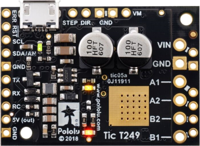
The Pololu Tic T249 Stepper Motor Controller is a versatile and efficient device designed to control the operation of stepper motors. It enables precise positioning and speed control by sending accurate pulses to the motor. The Tic T249 is ideal for applications requiring smooth and reliable stepper motor operation, such as robotics, 3D printing, CNC machines, and automated systems.
This controller supports multiple control interfaces, including USB, TTL serial, I²C, and analog voltage, making it highly adaptable to various projects. Its compact design and advanced features make it a popular choice for both hobbyists and professionals.
Explore Projects Built with Stepper Motor Controller


Explore Projects Built with Stepper Motor Controller
Technical Specifications
Below are the key technical details of the Pololu Tic T249 Stepper Motor Controller:
General Specifications
- Input Voltage Range: 10 V to 47 V
- Maximum Continuous Current: 4.5 A per phase
- Microstepping Modes: Full step, 1/2, 1/4, 1/8, 1/16, 1/32
- Control Interfaces: USB, TTL serial, I²C, analog voltage, RC (radio control)
- Operating Temperature: -40°C to 85°C
- Dimensions: 42 mm × 20 mm × 7 mm
- Weight: 5.5 g
Pin Configuration and Descriptions
The Tic T249 has a variety of pins for power, control, and communication. Below is a detailed pinout:
| Pin Name | Type | Description |
|---|---|---|
| VIN | Power Input | Main power supply input (10 V to 47 V). |
| GND | Power Ground | Ground connection for the power supply and logic. |
| STEP | Input | Step signal input for external step/dir control. |
| DIR | Input | Direction signal input for external step/dir control. |
| SCL | Input/Output | I²C clock line for communication. |
| SDA | Input/Output | I²C data line for communication. |
| TX | Output | TTL serial transmit line. |
| RX | Input | TTL serial receive line. |
| RC | Input | Radio control (RC) signal input. |
| AN | Input | Analog voltage input for speed or position control. |
| USB | Communication | USB interface for configuration and control. |
| FAULT | Output | Fault indicator output (active low). |
| RESET | Input | Resets the controller when pulled low. |
| CONFIG | Input | Used for advanced configuration during setup. |
Usage Instructions
How to Use the Tic T249 in a Circuit
- Power Supply: Connect a DC power supply (10 V to 47 V) to the VIN and GND pins. Ensure the power supply can provide sufficient current for your stepper motor.
- Motor Connection: Connect the stepper motor's four wires to the motor output terminals on the Tic T249. Refer to your motor's datasheet for the correct wiring.
- Control Interface: Choose a control method (e.g., USB, TTL serial, I²C, or analog voltage) and connect the appropriate pins to your microcontroller or computer.
- Configuration: Use the Pololu Tic Control Center software (available on the Pololu website) to configure the controller. Set parameters such as step mode, current limits, and control interface.
- Operation: Send commands via your chosen interface to control the motor's speed, direction, and position.
Important Considerations and Best Practices
- Current Limiting: Set the current limit in the Tic Control Center to match your stepper motor's rated current. This prevents overheating and damage to the motor.
- Cooling: If operating at high currents, ensure adequate cooling for the controller to avoid thermal shutdown.
- Decoupling Capacitors: Use a capacitor (e.g., 100 µF) across the VIN and GND pins to stabilize the power supply.
- Wiring: Keep motor and power wires as short as possible to minimize noise and voltage drops.
- Firmware Updates: Regularly check for firmware updates on the Pololu website to ensure optimal performance and compatibility.
Example: Using the Tic T249 with an Arduino UNO
Below is an example of controlling the Tic T249 via TTL serial using an Arduino UNO:
#include <SoftwareSerial.h>

// Define Arduino pins for software serial communication
#define TX_PIN 10  // Arduino pin connected to Tic T249 RX pin
#define RX_PIN 11  // Arduino pin connected to Tic T249 TX pin

// Create a SoftwareSerial object
SoftwareSerial ticSerial(RX_PIN, TX_PIN);

void setup() {
  // Initialize serial communication with the Tic T249
  ticSerial.begin(9600);

  // Set the Tic T249 to "Exit Safe Start" mode
  sendCommand(0x83);  // Command 0x83 exits safe start mode

  // Set target position (example: 2000 steps)
  setTargetPosition(2000);
}

void loop() {
  // Add your main code here (e.g., change position or speed dynamically)
}

// Function to send a single-byte command to the Tic T249
void sendCommand(uint8_t command) {
  ticSerial.write(command);
}

// Function to set the target position of the stepper motor
void setTargetPosition(int32_t position) {
  ticSerial.write(0xE0);  // Command 0xE0 sets target position
  ticSerial.write((uint8_t)(position & 0xFF));         // Low byte
  ticSerial.write((uint8_t)((position >> 8) & 0xFF));  // Middle byte
  ticSerial.write((uint8_t)((position >> 16) & 0xFF)); // High byte
  ticSerial.write((uint8_t)((position >> 24) & 0xFF)); // Highest byte
}
Notes:
- Ensure the Tic T249 is configured for TTL serial control in the Tic Control Center.
- Use a logic level shifter if your Arduino operates at 5 V logic and the Tic T249 is configured for 3.3 V logic.
Troubleshooting and FAQs
Common Issues and Solutions
Motor Not Moving:
- Verify the power supply voltage and current are sufficient.
- Check motor wiring and ensure it matches the motor's datasheet.
- Ensure the Tic T249 is not in "Safe Start" mode. Exit Safe Start using the appropriate command.
Overheating:
- Reduce the current limit in the Tic Control Center.
- Add a heatsink or fan to improve cooling.
Communication Errors:
- Check the wiring for the selected control interface (e.g., USB, TTL serial, I²C).
- Ensure the baud rate and other communication settings match between the Tic T249 and your microcontroller.
Fault Indicator Active:
- Check for overcurrent, undervoltage, or thermal shutdown conditions.
- Use the Tic Control Center to diagnose the fault.
FAQs
Can I use the Tic T249 with a 5 V stepper motor? Yes, but ensure the power supply voltage is within the Tic T249's range (10 V to 47 V) and set the current limit appropriately.
What is the maximum step rate supported? The Tic T249 supports step rates up to 500,000 steps per second.
Can I control multiple Tic T249 controllers with one microcontroller? Yes, you can use unique addresses for each controller when using I²C or separate serial lines for TTL communication.
For additional support, refer to the Pololu Tic T249 user manual or contact Pololu's technical support team.