Cirkit Designer Logo
Cirkit Designer
Your all-in-one circuit design IDE
Home / 
Component Documentation

How to Use ESP32 WROOM 32: Examples, Pinouts, and Specs

Image of ESP32 WROOM 32
Cirkit Designer LogoDesign with ESP32 WROOM 32 in Cirkit Designer

Introduction

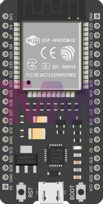
The ESP32 WROOM 32, manufactured by Microcontroller (Part ID: ESP32), is a powerful and versatile microcontroller module. It features integrated Wi-Fi and Bluetooth capabilities, making it an excellent choice for Internet of Things (IoT) applications, smart devices, and embedded systems. With its dual-core processor, low power consumption, and extensive GPIO options, the ESP32 WROOM 32 is designed to handle a wide range of tasks, from simple sensor monitoring to complex data processing.

Explore Projects Built with ESP32 WROOM 32

Use Cirkit Designer to design, explore, and prototype these projects online. Some projects support real-time simulation. Click "Open Project" to start designing instantly!
ESP32-Based GPS Tracker with SD Card Logging and Barometric Sensor
Image of gps projekt circuit: A project utilizing ESP32 WROOM 32 in a practical application
This circuit features an ESP32 Wroom Dev Kit as the main microcontroller, interfaced with an MPL3115A2 sensor for pressure and temperature readings, and a Neo 6M GPS module for location tracking. The ESP32 is also connected to an SD card reader for data logging purposes. A voltage regulator is used to step down the USB power supply to 3.3V, which powers the ESP32, the sensor, and the SD card reader.
Cirkit Designer LogoOpen Project in Cirkit Designer
ESP32-Based Infrared Proximity Sensing System
Image of ir sensor: A project utilizing ESP32 WROOM 32 in a practical application
This circuit features an ESP32 Wroom microcontroller connected to an Infrared Proximity Sensor. The ESP32's GPIO33 is interfaced with the sensor's output, allowing the microcontroller to read proximity data. The sensor is powered by the ESP32's 5V output, and both devices share a common ground.
Cirkit Designer LogoOpen Project in Cirkit Designer
ESP32-Based Multi-Sensor Health Monitoring System with Bluetooth Connectivity
Image of circuit diagram: A project utilizing ESP32 WROOM 32 in a practical application
This circuit features an ESP32-WROOM-32UE microcontroller as the central processing unit, interfacing with a variety of sensors and modules. It includes a MAX30100 pulse oximeter and heart-rate sensor, an MLX90614 infrared thermometer, an HC-05 Bluetooth module for wireless communication, and a Neo 6M GPS module for location tracking. All components are powered by a common voltage supply and are connected to specific GPIO pins on the ESP32 for data exchange, with the sensors using I2C communication and the modules using UART.
Cirkit Designer LogoOpen Project in Cirkit Designer
ESP32-Based Smart Medication Dispenser with Wi-Fi Connectivity and RTC Scheduling
Image of VAC: A project utilizing ESP32 WROOM 32 in a practical application
This circuit features an ESP32 microcontroller interfaced with a membrane matrix keypad, an I2C LCD screen, a real-time clock (RTC DS3231), two servos, a buzzer, and additional components like resistors and capacitors for stabilization and current limiting. The ESP32 runs embedded code to manage a keypad-based user interface, display information on the LCD, and control alarms and servo positions based on the RTC input, likely for a timed locking/unlocking mechanism or scheduled alert system. The circuit includes a WiFi setup for remote connectivity and EEPROM for non-volatile storage of configurations and schedules.
Cirkit Designer LogoOpen Project in Cirkit Designer

Explore Projects Built with ESP32 WROOM 32

Use Cirkit Designer to design, explore, and prototype these projects online. Some projects support real-time simulation. Click "Open Project" to start designing instantly!
Image of gps projekt circuit: A project utilizing ESP32 WROOM 32 in a practical application
ESP32-Based GPS Tracker with SD Card Logging and Barometric Sensor
This circuit features an ESP32 Wroom Dev Kit as the main microcontroller, interfaced with an MPL3115A2 sensor for pressure and temperature readings, and a Neo 6M GPS module for location tracking. The ESP32 is also connected to an SD card reader for data logging purposes. A voltage regulator is used to step down the USB power supply to 3.3V, which powers the ESP32, the sensor, and the SD card reader.
Cirkit Designer LogoOpen Project in Cirkit Designer
Image of ir sensor: A project utilizing ESP32 WROOM 32 in a practical application
ESP32-Based Infrared Proximity Sensing System
This circuit features an ESP32 Wroom microcontroller connected to an Infrared Proximity Sensor. The ESP32's GPIO33 is interfaced with the sensor's output, allowing the microcontroller to read proximity data. The sensor is powered by the ESP32's 5V output, and both devices share a common ground.
Cirkit Designer LogoOpen Project in Cirkit Designer
Image of circuit diagram: A project utilizing ESP32 WROOM 32 in a practical application
ESP32-Based Multi-Sensor Health Monitoring System with Bluetooth Connectivity
This circuit features an ESP32-WROOM-32UE microcontroller as the central processing unit, interfacing with a variety of sensors and modules. It includes a MAX30100 pulse oximeter and heart-rate sensor, an MLX90614 infrared thermometer, an HC-05 Bluetooth module for wireless communication, and a Neo 6M GPS module for location tracking. All components are powered by a common voltage supply and are connected to specific GPIO pins on the ESP32 for data exchange, with the sensors using I2C communication and the modules using UART.
Cirkit Designer LogoOpen Project in Cirkit Designer
Image of VAC: A project utilizing ESP32 WROOM 32 in a practical application
ESP32-Based Smart Medication Dispenser with Wi-Fi Connectivity and RTC Scheduling
This circuit features an ESP32 microcontroller interfaced with a membrane matrix keypad, an I2C LCD screen, a real-time clock (RTC DS3231), two servos, a buzzer, and additional components like resistors and capacitors for stabilization and current limiting. The ESP32 runs embedded code to manage a keypad-based user interface, display information on the LCD, and control alarms and servo positions based on the RTC input, likely for a timed locking/unlocking mechanism or scheduled alert system. The circuit includes a WiFi setup for remote connectivity and EEPROM for non-volatile storage of configurations and schedules.
Cirkit Designer LogoOpen Project in Cirkit Designer

Common Applications and Use Cases

  • IoT devices and smart home automation
  • Wireless sensor networks
  • Wearable technology
  • Industrial automation and control systems
  • Robotics and drones
  • Real-time data logging and monitoring

Technical Specifications

The ESP32 WROOM 32 is packed with features that make it a standout choice for developers. Below are its key technical specifications:

General Specifications

Parameter Value
Microcontroller Tensilica Xtensa LX6 Dual-Core Processor
Clock Speed Up to 240 MHz
Flash Memory 4 MB (external SPI flash)
SRAM 520 KB
Wi-Fi 802.11 b/g/n (2.4 GHz)
Bluetooth v4.2 BR/EDR and BLE
Operating Voltage 3.3 V
Power Consumption Ultra-low power modes available
Operating Temperature -40°C to +85°C

Pin Configuration and Descriptions

The ESP32 WROOM 32 module has 38 pins. Below is a summary of the pin configuration:

Pin Number Pin Name Description
1 EN Enable pin. Active high. Resets the chip when pulled low.
2 IO0 GPIO0. Used to enter bootloader mode when pulled low during reset.
3 IO1 (TX0) GPIO1. UART0 TX pin.
4 IO3 (RX0) GPIO3. UART0 RX pin.
5 IO4 GPIO4. General-purpose I/O pin.
6 IO5 GPIO5. General-purpose I/O pin.
7 IO12 GPIO12. Can be used as an ADC or touch sensor input.
8 IO13 GPIO13. Can be used as an ADC or touch sensor input.
9 IO14 GPIO14. PWM-capable GPIO pin.
10 IO15 GPIO15. PWM-capable GPIO pin.
... ... ... (Refer to the full datasheet for all pin details.)

Note: Some pins have specific functions during boot (e.g., GPIO0 for bootloader mode). Refer to the datasheet for detailed pin behavior.

Usage Instructions

How to Use the ESP32 WROOM 32 in a Circuit

  1. Powering the Module:

    • The ESP32 WROOM 32 operates at 3.3 V. Ensure your power supply provides a stable 3.3 V to the VCC pin.
    • Avoid supplying 5 V directly to the module, as it may damage the chip.
  2. Connecting to a Microcontroller or PC:

    • Use a USB-to-Serial adapter (e.g., FTDI or CP2102) to connect the ESP32 to your PC for programming.
    • Connect the TX pin of the adapter to the RX pin of the ESP32 and the RX pin of the adapter to the TX pin of the ESP32.
  3. Programming the ESP32:

    • The ESP32 can be programmed using the Arduino IDE or the ESP-IDF framework.
    • To upload code, ensure GPIO0 is pulled low during reset to enter bootloader mode.
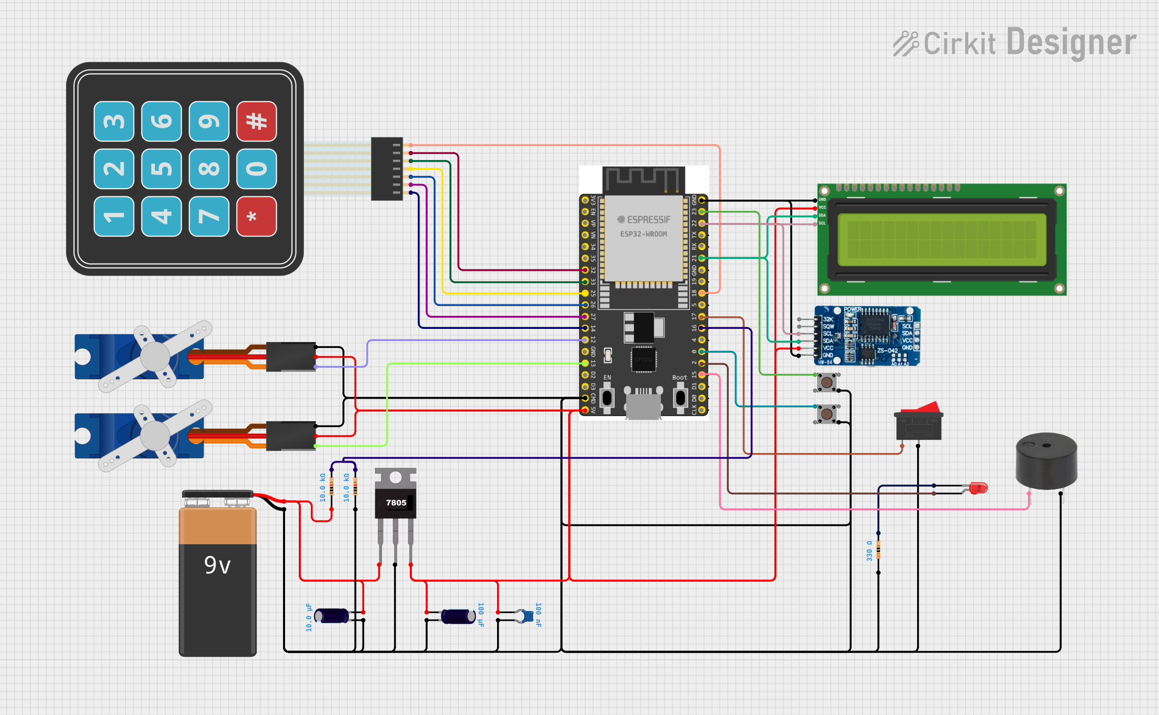
  4. Connecting Peripherals:

    • Use the GPIO pins to connect sensors, actuators, or other peripherals.
    • For analog sensors, use the ADC pins (e.g., GPIO32, GPIO33).

Important Considerations and Best Practices

  • Voltage Levels: Ensure all connected devices operate at 3.3 V logic levels. Use level shifters if interfacing with 5 V devices.
  • Decoupling Capacitors: Place a 0.1 µF capacitor close to the power pins to stabilize the power supply.
  • Antenna Placement: Avoid placing metal objects near the onboard antenna to ensure optimal Wi-Fi and Bluetooth performance.
  • Boot Mode: To enter bootloader mode, connect GPIO0 to GND and reset the module.

Example Code for Arduino UNO

Below is an example of how to use the ESP32 WROOM 32 with the Arduino IDE to blink an LED:

// Example: Blink an LED connected to GPIO2 on the ESP32 WROOM 32

// Define the GPIO pin for the LED
#define LED_PIN 2

void setup() {
  // Initialize the LED pin as an output
  pinMode(LED_PIN, OUTPUT);
}

void loop() {
  // Turn the LED on
  digitalWrite(LED_PIN, HIGH);
  delay(1000); // Wait for 1 second

  // Turn the LED off
  digitalWrite(LED_PIN, LOW);
  delay(1000); // Wait for 1 second
}

Note: Ensure the LED is connected to GPIO2 with a current-limiting resistor (e.g., 220 Ω).

Troubleshooting and FAQs

Common Issues and Solutions

  1. ESP32 Not Detected by PC:

    • Ensure the USB-to-Serial adapter drivers are installed.
    • Check the connections between the adapter and the ESP32.
  2. Code Upload Fails:

    • Verify that GPIO0 is pulled low during reset to enter bootloader mode.
    • Check the baud rate in the Arduino IDE (default: 115200).
  3. Wi-Fi Connection Issues:

    • Ensure the correct SSID and password are used in the code.
    • Check for interference from other devices on the same Wi-Fi channel.
  4. Module Overheating:

    • Verify the power supply voltage is 3.3 V.
    • Avoid overloading the GPIO pins with excessive current.

FAQs

  • Q: Can the ESP32 WROOM 32 operate on 5 V?
    A: No, the ESP32 operates at 3.3 V. Use a voltage regulator or level shifter for 5 V systems.

  • Q: How many GPIO pins are available?
    A: The ESP32 WROOM 32 has 34 GPIO pins, but some are reserved for specific functions.

  • Q: Can I use the ESP32 with Bluetooth and Wi-Fi simultaneously?
    A: Yes, the ESP32 supports simultaneous use of Bluetooth and Wi-Fi.

  • Q: What is the maximum range of the Wi-Fi module?
    A: The range depends on the environment but typically extends up to 100 meters in open space.

For more detailed information, refer to the official ESP32 datasheet and programming guides.