How to Use 74LS47N: Examples, Pinouts, and Specs
Introduction
The SN74LS47N, manufactured by Texas Instruments, is a BCD (Binary-Coded Decimal) to 7-segment decoder/driver IC. This component is designed to convert a 4-bit BCD input into the corresponding segment control signals required to display numbers 0-9 on a 7-segment display. It is widely used in digital clocks, calculators, and other devices that require numerical displays.
Explore Projects Built with 74LS47N


Explore Projects Built with 74LS47N
Technical Specifications
Key Technical Details
| Parameter | Value |
|---|---|
| Supply Voltage | 4.75V to 5.25V |
| Input Voltage | 0V to 5.25V |
| Output Voltage | 0V to 15V |
| Output Current | 24mA (per segment) |
| Power Dissipation | 100mW |
| Operating Temperature | 0°C to 70°C |
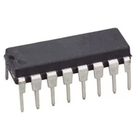
| Package Type | DIP-16 |
Pin Configuration and Descriptions
| Pin No. | Pin Name | Description |
|---|---|---|
| 1 | A | BCD Input A (LSB) |
| 2 | B | BCD Input B |
| 3 | C | BCD Input C |
| 4 | D | BCD Input D (MSB) |
| 5 | a | Segment a output |
| 6 | b | Segment b output |
| 7 | c | Segment c output |
| 8 | GND | Ground |
| 9 | d | Segment d output |
| 10 | e | Segment e output |
| 11 | f | Segment f output |
| 12 | g | Segment g output |
| 13 | LT | Lamp Test (active low) |
| 14 | BI/RBO | Blanking Input/Ripple Blanking Output (active low) |
| 15 | RBI | Ripple Blanking Input (active low) |
| 16 | VCC | Supply Voltage |
Usage Instructions
How to Use the SN74LS47N in a Circuit
- Power Supply: Connect pin 16 (VCC) to a 5V power supply and pin 8 (GND) to ground.
- BCD Inputs: Connect the BCD inputs (pins 1, 2, 3, and 4) to the digital outputs of a microcontroller or other digital logic source.
- 7-Segment Display: Connect the segment outputs (pins 5, 6, 7, 9, 10, 11, and 12) to the corresponding segments of a common-anode 7-segment display.
- Control Pins:
- Connect pin 13 (LT) to VCC if the lamp test function is not needed.
- Connect pin 14 (BI/RBO) to VCC if blanking is not required.
- Connect pin 15 (RBI) to VCC if ripple blanking is not required.
Important Considerations and Best Practices
- Ensure that the power supply voltage is within the specified range (4.75V to 5.25V).
- Use current-limiting resistors for each segment to prevent excessive current draw.
- Avoid leaving unused inputs floating; connect them to a defined logic level (either VCC or GND).
Example Circuit with Arduino UNO
// Arduino UNO to SN74LS47N BCD to 7-Segment Display Example

// Define BCD input pins
const int bcdA = 2;
const int bcdB = 3;
const int bcdC = 4;
const int bcdD = 5;

// Number to display (0-9)
int number = 0;

void setup() {
  // Set BCD pins as outputs
  pinMode(bcdA, OUTPUT);
  pinMode(bcdB, OUTPUT);
  pinMode(bcdC, OUTPUT);
  pinMode(bcdD, OUTPUT);
}

void loop() {
  // Display the number on the 7-segment display
  displayNumber(number);

  // Increment the number
  number++;
  if (number > 9) {
    number = 0;
  }

  // Wait for 1 second
  delay(1000);
}

void displayNumber(int num) {
  // Convert the number to BCD and set the pins
  digitalWrite(bcdA, num & 0x01);
  digitalWrite(bcdB, (num >> 1) & 0x01);
  digitalWrite(bcdC, (num >> 2) & 0x01);
  digitalWrite(bcdD, (num >> 3) & 0x01);
}
Troubleshooting and FAQs
Common Issues
No Display Output:
- Ensure that the power supply is connected and providing the correct voltage.
- Check all connections to the 7-segment display and the SN74LS47N.
- Verify that the BCD inputs are receiving the correct signals.
Incorrect Digits Displayed:
- Ensure that the BCD inputs are correctly connected and providing the correct binary values.
- Check for any loose or incorrect connections.
Dim or Flickering Segments:
- Verify that the current-limiting resistors are of the correct value.
- Ensure that the power supply can provide sufficient current for the display.
Solutions and Tips for Troubleshooting
- Use a Multimeter: Check the voltage levels at various points in the circuit to ensure they are within the expected range.
- Check Connections: Double-check all wiring and connections to ensure they are secure and correct.
- Test Individual Components: If possible, test the 7-segment display and the SN74LS47N separately to isolate the issue.
FAQs
Q: Can the SN74LS47N drive a common-cathode 7-segment display? A: No, the SN74LS47N is designed to drive common-anode 7-segment displays.
Q: What is the purpose of the LT, BI/RBO, and RBI pins? A:
- LT (Lamp Test) is used to test all segments by lighting them up when pulled low.
- BI/RBO (Blanking Input/Ripple Blanking Output) is used to blank the display or cascade multiple decoders.
- RBI (Ripple Blanking Input) is used to blank leading zeros in multi-digit displays.
Q: Can I use the SN74LS47N with a 3.3V microcontroller? A: The SN74LS47N is designed for a 5V supply. Using it with a 3.3V microcontroller may require level shifters to ensure proper operation.
This documentation provides a comprehensive guide to using the SN74LS47N BCD to 7-segment decoder/driver IC. By following the instructions and best practices outlined, users can effectively integrate this component into their projects.