Cirkit Designer Logo
Cirkit Designer
Your all-in-one circuit design IDE
Home / 
Component Documentation

How to Use STM32F3DISCOVERY: Examples, Pinouts, and Specs

Image of STM32F3DISCOVERY
Cirkit Designer LogoDesign with STM32F3DISCOVERY in Cirkit Designer

Introduction

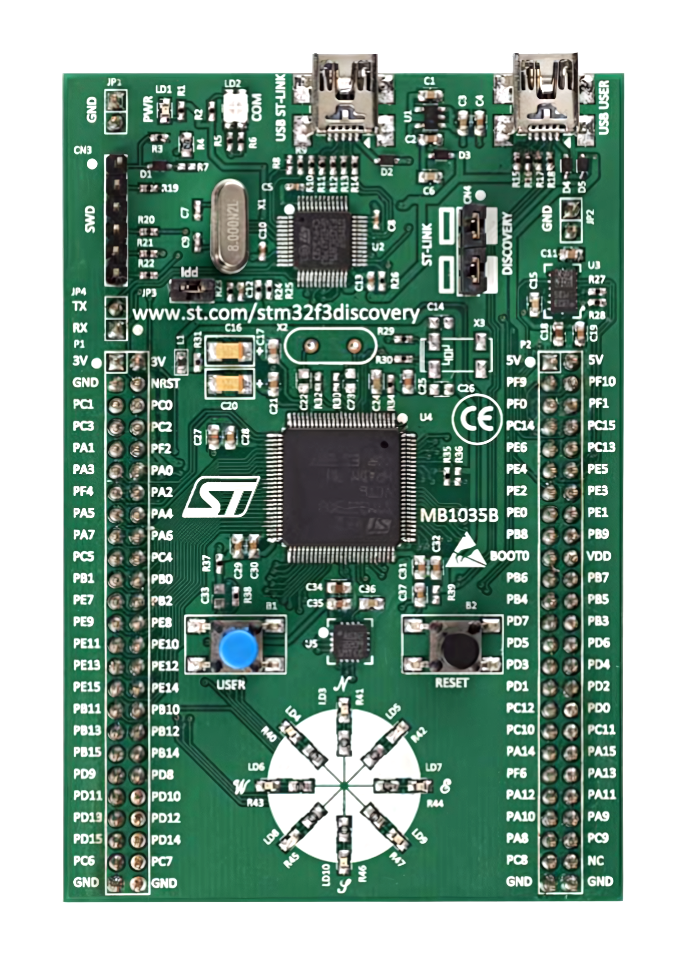
The STM32F3DISCOVERY is a development board manufactured by STMicroelectronics and features the STM32F303 microcontroller. This board is designed for prototyping and testing applications in embedded systems. It is equipped with a wide range of peripherals and interfaces, making it an excellent choice for developers working on motor control, industrial applications, medical devices, and consumer electronics.

Explore Projects Built with STM32F3DISCOVERY

Use Cirkit Designer to design, explore, and prototype these projects online. Some projects support real-time simulation. Click "Open Project" to start designing instantly!
STM32 Nucleo F303RE Controlled Ultrasonic Sensing with RGB Feedback and I2C LCD Display
Image of CS435-final: A project utilizing STM32F3DISCOVERY in a practical application
This circuit features a STM32 Nucleo F303RE microcontroller interfaced with three HC-SR04 ultrasonic sensors for distance measurement and a 20x4 LCD display over I2C for data output. Additionally, there is a WS2812 RGB LED strip controlled by the microcontroller for visual feedback. The power supply provides a common 5V to the LCD, ultrasonic sensors, LED strip, and the microcontroller's +5V input, with all components sharing a common ground.
Cirkit Designer LogoOpen Project in Cirkit Designer
STM32F103C8T6-Based Spectral Sensor with ST7735S Display and Pushbutton Control
Image of ColorSensor: A project utilizing STM32F3DISCOVERY in a practical application
This circuit features an STM32F103C8T6 microcontroller interfaced with a China ST7735S 160x128 display and two spectral sensors (Adafruit AS7262 and AS7261). It also includes two pushbuttons for user input, with the microcontroller managing the display and sensor data processing.
Cirkit Designer LogoOpen Project in Cirkit Designer
STM32F103C8T6 Bluetooth-Controlled Arcade Joystick Interface
Image of RC카 조이스틱: A project utilizing STM32F3DISCOVERY in a practical application
This circuit features an STM32F103C8T6 microcontroller interfaced with a Bluetooth HC-06 module for wireless communication and an Adafruit Arcade Joystick for user input. The microcontroller's pins B0 and B10 are connected to the TXD and RXD pins of the Bluetooth module, enabling serial communication, while pins B14 and B15 interface with the joystick's directional controls. The circuit is powered by a battery, with power distribution managed through the microcontroller's 3.3V pin and common ground connections.
Cirkit Designer LogoOpen Project in Cirkit Designer
Solar-Powered STM32-Based Automation System with Matrix Keypad and RTC
Image of soloar cleaner : A project utilizing STM32F3DISCOVERY in a practical application
This circuit features an STM32F103C8T6 microcontroller interfaced with a membrane matrix keypad for input, an RTC DS3231 for real-time clock functionality, and a 16x2 I2C LCD for display. It controls four 12V geared motors through two MD20 CYTRON motor drivers, with the motor power supplied by a 12V battery regulated by a buck converter. The battery is charged via a solar panel connected through a solar charge controller, ensuring a renewable energy source for the system.
Cirkit Designer LogoOpen Project in Cirkit Designer

Explore Projects Built with STM32F3DISCOVERY

Use Cirkit Designer to design, explore, and prototype these projects online. Some projects support real-time simulation. Click "Open Project" to start designing instantly!
Image of CS435-final: A project utilizing STM32F3DISCOVERY in a practical application
STM32 Nucleo F303RE Controlled Ultrasonic Sensing with RGB Feedback and I2C LCD Display
This circuit features a STM32 Nucleo F303RE microcontroller interfaced with three HC-SR04 ultrasonic sensors for distance measurement and a 20x4 LCD display over I2C for data output. Additionally, there is a WS2812 RGB LED strip controlled by the microcontroller for visual feedback. The power supply provides a common 5V to the LCD, ultrasonic sensors, LED strip, and the microcontroller's +5V input, with all components sharing a common ground.
Cirkit Designer LogoOpen Project in Cirkit Designer
Image of ColorSensor: A project utilizing STM32F3DISCOVERY in a practical application
STM32F103C8T6-Based Spectral Sensor with ST7735S Display and Pushbutton Control
This circuit features an STM32F103C8T6 microcontroller interfaced with a China ST7735S 160x128 display and two spectral sensors (Adafruit AS7262 and AS7261). It also includes two pushbuttons for user input, with the microcontroller managing the display and sensor data processing.
Cirkit Designer LogoOpen Project in Cirkit Designer
Image of RC카 조이스틱: A project utilizing STM32F3DISCOVERY in a practical application
STM32F103C8T6 Bluetooth-Controlled Arcade Joystick Interface
This circuit features an STM32F103C8T6 microcontroller interfaced with a Bluetooth HC-06 module for wireless communication and an Adafruit Arcade Joystick for user input. The microcontroller's pins B0 and B10 are connected to the TXD and RXD pins of the Bluetooth module, enabling serial communication, while pins B14 and B15 interface with the joystick's directional controls. The circuit is powered by a battery, with power distribution managed through the microcontroller's 3.3V pin and common ground connections.
Cirkit Designer LogoOpen Project in Cirkit Designer
Image of soloar cleaner : A project utilizing STM32F3DISCOVERY in a practical application
Solar-Powered STM32-Based Automation System with Matrix Keypad and RTC
This circuit features an STM32F103C8T6 microcontroller interfaced with a membrane matrix keypad for input, an RTC DS3231 for real-time clock functionality, and a 16x2 I2C LCD for display. It controls four 12V geared motors through two MD20 CYTRON motor drivers, with the motor power supplied by a 12V battery regulated by a buck converter. The battery is charged via a solar panel connected through a solar charge controller, ensuring a renewable energy source for the system.
Cirkit Designer LogoOpen Project in Cirkit Designer

Common Applications and Use Cases

  • Motor control and industrial automation
  • Sensor interfacing and data acquisition
  • Embedded system prototyping
  • Educational purposes for learning ARM Cortex-M4 architecture
  • Real-time control systems

Technical Specifications

The STM32F3DISCOVERY board is built around the STM32F303VCT6 microcontroller, which is based on the ARM Cortex-M4 core. Below are the key technical details:

Key Features

  • Microcontroller: STM32F303VCT6 (ARM Cortex-M4, 32-bit)
  • Clock Speed: Up to 72 MHz
  • Flash Memory: 256 KB
  • SRAM: 48 KB
  • Operating Voltage: 3.0V to 3.6V
  • Interfaces:
    • USB 2.0 Full-Speed
    • I2C, SPI, USART
    • CAN bus
  • Onboard Peripherals:
    • 3-axis gyroscope and 3-axis accelerometer (LSM303DLHC)
    • 8 LEDs for user interaction
    • 2 push buttons (User and Reset)
    • ST-LINK/V2 debugger and programmer
  • Power Supply: USB-powered or external 5V supply
  • Dimensions: 84 mm x 54 mm

Pin Configuration and Descriptions

The STM32F3DISCOVERY board exposes several GPIO pins and interfaces through its headers. Below is a summary of the pin configuration:

Pin Name Description Alternate Function
PA0 GPIO, ADC Input, Timer Input WKUP (Wakeup Pin)
PA1 GPIO, ADC Input, Timer Input
PA9 USART1_TX
PA10 USART1_RX
PB6 I2C1_SCL
PB7 I2C1_SDA
PC13 GPIO (User Button)
PC0-PC15 GPIO
PD0-PD15 GPIO

For a complete pinout, refer to the official STM32F3DISCOVERY datasheet.

Usage Instructions

The STM32F3DISCOVERY board is designed to simplify the development process. Below are the steps to get started and best practices for using the board.

Getting Started

  1. Powering the Board:

    • Connect the board to your computer using a micro-USB cable. The board will be powered via USB.
    • Alternatively, you can supply 5V through the external power header.
  2. Programming the Board:

    • Use the onboard ST-LINK/V2 debugger to program the microcontroller.
    • Compatible IDEs include STM32CubeIDE, Keil uVision, and IAR Embedded Workbench.
  3. Connecting Peripherals:

    • Use the GPIO headers to connect external sensors, actuators, or other devices.
    • Ensure that the voltage levels of connected peripherals are compatible with the board's 3.3V logic.
  4. Flashing Code:

    • Write your code in the IDE of your choice.
    • Compile and flash the code to the board using the ST-LINK interface.

Example Code for Arduino IDE

The STM32F3DISCOVERY can be programmed using the Arduino IDE with the STM32 core installed. Below is an example of blinking an onboard LED:

// Example: Blink the onboard LED (connected to PC8)

// Define the pin for the onboard LED
#define LED_PIN PC8

void setup() {
  pinMode(LED_PIN, OUTPUT); // Set the LED pin as an output
}

void loop() {
  digitalWrite(LED_PIN, HIGH); // Turn the LED on
  delay(500);                  // Wait for 500 milliseconds
  digitalWrite(LED_PIN, LOW);  // Turn the LED off
  delay(500);                  // Wait for 500 milliseconds
}

Best Practices

  • Always ensure the board is powered off before connecting or disconnecting peripherals.
  • Use proper ESD precautions when handling the board to avoid damaging sensitive components.
  • Avoid exceeding the voltage and current ratings of the GPIO pins.
  • Use decoupling capacitors when connecting external devices to reduce noise.

Troubleshooting and FAQs

Common Issues and Solutions

  1. The board is not detected by the computer:

    • Ensure the USB cable is functional and properly connected.
    • Check if the ST-LINK drivers are installed on your computer.
  2. Code does not run after flashing:

    • Verify that the correct microcontroller is selected in your IDE.
    • Ensure the code is compiled without errors.
    • Check the power supply to the board.
  3. Peripherals are not working as expected:

    • Double-check the pin connections and configurations in your code.
    • Ensure the voltage levels of connected peripherals are compatible with the board.
  4. LEDs are not blinking:

    • Verify that the correct pin is defined in your code.
    • Check if the onboard LED is functional by running a simple test program.

FAQs

Q: Can I power the board using an external power supply?
A: Yes, the board can be powered using an external 5V supply through the power header.

Q: Is the STM32F3DISCOVERY compatible with Arduino libraries?
A: Yes, with the STM32 core installed in the Arduino IDE, you can use many Arduino libraries.

Q: How do I reset the board?
A: Press the Reset button (labeled "RESET") on the board to restart the microcontroller.

Q: Can I use the board for motor control applications?
A: Yes, the STM32F3DISCOVERY is well-suited for motor control applications due to its advanced timers and PWM capabilities.

By following this documentation, you can effectively use the STM32F3DISCOVERY board for your embedded system projects. For more details, refer to the official user manual and datasheet provided by STMicroelectronics.