How to Use 8-channel-mux: Examples, Pinouts, and Specs
Introduction
An 8-channel multiplexer (mux) is a digital switching device that enables the selection of one input signal from up to eight available inputs and routes it to a single output line. The selection is controlled by a set of binary control signals. This component is widely used in applications such as data routing, signal processing, communication systems, and microcontroller-based projects.
Explore Projects Built with 8-channel-mux


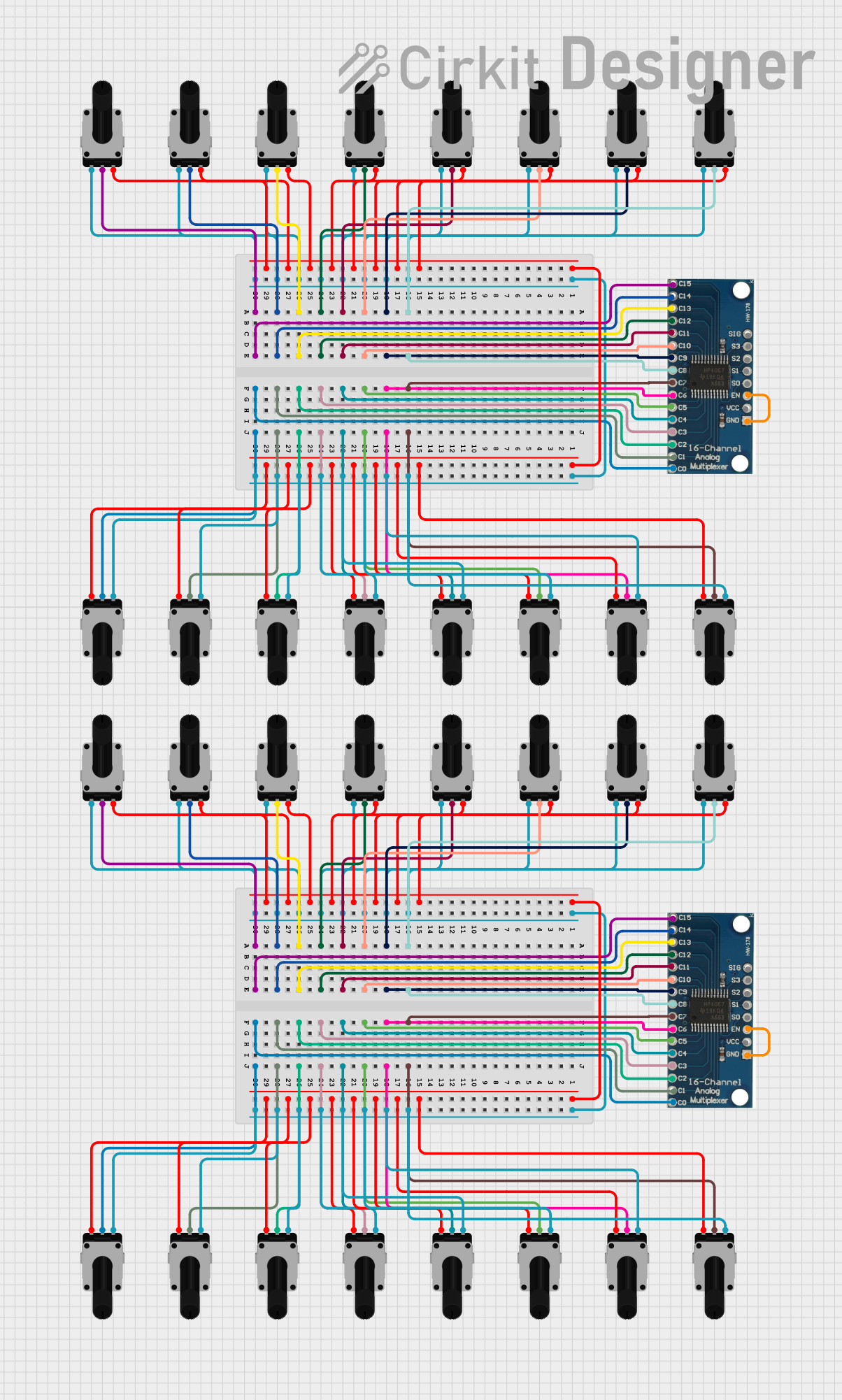
Explore Projects Built with 8-channel-mux
Common Applications and Use Cases
- Signal selection in microcontroller projects
- Data acquisition systems
- Communication systems for channel selection
- Expanding the number of input/output pins in microcontrollers
- Audio and video signal routing
Technical Specifications
The following table outlines the key technical details of the 8-channel multiplexer:
| Parameter | Value |
|---|---|
| Manufacturer | ARDUINO |
| Part ID | UNO |
| Number of Channels | 8 |
| Supply Voltage (Vcc) | 2V to 6V |
| Input Voltage Range | 0V to Vcc |
| Control Signal Levels | TTL/CMOS compatible |
| Propagation Delay | ~10ns to 50ns (varies by model) |
| Power Consumption | Low power (varies by usage) |
| Operating Temperature | -40°C to +85°C |
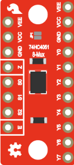
Pin Configuration and Descriptions
The 8-channel mux typically has the following pin configuration:
| Pin Number | Pin Name | Description |
|---|---|---|
| 1 | S0 | Control signal 0 (Least Significant Bit of the selection input) |
| 2 | S1 | Control signal 1 |
| 3 | S2 | Control signal 2 (Most Significant Bit of the selection input) |
| 4 | IN0 | Input channel 0 |
| 5 | IN1 | Input channel 1 |
| 6 | IN2 | Input channel 2 |
| 7 | IN3 | Input channel 3 |
| 8 | IN4 | Input channel 4 |
| 9 | IN5 | Input channel 5 |
| 10 | IN6 | Input channel 6 |
| 11 | IN7 | Input channel 7 |
| 12 | OUT | Output signal (selected input is routed here) |
| 13 | GND | Ground |
| 14 | Vcc | Supply voltage |
Usage Instructions
How to Use the 8-Channel Mux in a Circuit
- Power the Mux: Connect the
Vccpin to a suitable power supply (e.g., 5V for Arduino UNO) and theGNDpin to ground. - Connect Input Signals: Attach up to eight input signals to the
IN0toIN7pins. - Control Signal Setup: Use three control pins (
S0,S1,S2) to select the desired input channel. The binary combination of these pins determines which input is routed to the output. - Output Connection: Connect the
OUTpin to the desired destination (e.g., an ADC pin on a microcontroller). - Control Logic: Use a microcontroller or external logic to set the control signals (
S0,S1,S2) based on the desired input channel.
Important Considerations and Best Practices
- Ensure the input voltage levels are within the specified range (0V to Vcc).
- Use pull-down resistors on control pins if they are left floating to avoid unpredictable behavior.
- Minimize noise by keeping signal lines short and using decoupling capacitors near the power supply pins.
- Verify the propagation delay of the mux to ensure it meets the timing requirements of your application.
Example: Connecting the 8-Channel Mux to an Arduino UNO
Below is an example of how to connect and control the 8-channel mux using an Arduino UNO:
Circuit Connections
- Connect
Vccto the 5V pin on the Arduino UNO. - Connect
GNDto the GND pin on the Arduino UNO. - Connect
S0,S1, andS2to digital pins 2, 3, and 4 on the Arduino UNO, respectively. - Connect
OUTto the A0 (analog input) pin on the Arduino UNO. - Connect input signals to
IN0throughIN7.
Arduino Code Example
// Define control pins for the 8-channel mux
const int S0 = 2; // Control signal 0
const int S1 = 3; // Control signal 1
const int S2 = 4; // Control signal 2

// Define the output pin of the mux
const int MUX_OUT = A0; // Analog input pin on Arduino

void setup() {
  // Set control pins as outputs
  pinMode(S0, OUTPUT);
  pinMode(S1, OUTPUT);
  pinMode(S2, OUTPUT);

  // Initialize serial communication for debugging
  Serial.begin(9600);
}

void loop() {
  for (int channel = 0; channel < 8; channel++) {
    // Set the control pins to select the desired channel
    digitalWrite(S0, channel & 0x01); // Least significant bit
    digitalWrite(S1, (channel >> 1) & 0x01); // Second bit
    digitalWrite(S2, (channel >> 2) & 0x01); // Most significant bit

    // Read the selected input signal
    int signalValue = analogRead(MUX_OUT);

    // Print the channel number and signal value to the serial monitor
    Serial.print("Channel ");
    Serial.print(channel);
    Serial.print(": ");
    Serial.println(signalValue);

    // Wait for a short period before switching to the next channel
    delay(500);
  }
}
Troubleshooting and FAQs
Common Issues and Solutions
No Output Signal:
- Verify that the
VccandGNDpins are properly connected. - Check the control signal connections and ensure they are set correctly.
- Ensure the input signal is within the specified voltage range.
- Verify that the
Unstable or Noisy Output:
- Use decoupling capacitors near the power supply pins to reduce noise.
- Keep signal lines as short as possible to minimize interference.
Incorrect Channel Selection:
- Double-check the binary values sent to the control pins (
S0,S1,S2). - Ensure the control pins are not left floating; use pull-down resistors if necessary.
- Double-check the binary values sent to the control pins (
FAQs
Q: Can I use the 8-channel mux with a 3.3V microcontroller?
A: Yes, the mux supports a supply voltage range of 2V to 6V. Ensure the input signals and control signals are within the 3.3V logic level.
Q: What happens if multiple input channels are active simultaneously?
A: The mux will only route the input corresponding to the binary value of the control signals. Other inputs will be ignored.
Q: Can the mux handle analog signals?
A: Yes, the mux can route analog signals as long as they are within the specified voltage range (0V to Vcc).