How to Use Wattmeter: Examples, Pinouts, and Specs
Introduction
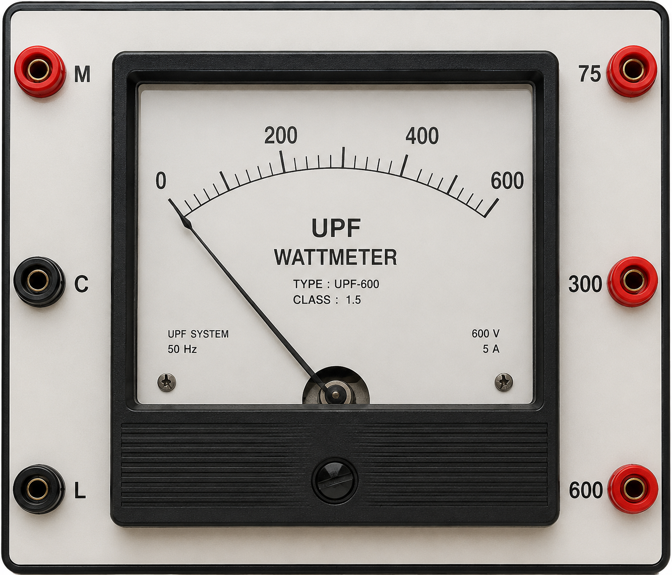
A wattmeter is an electronic device used to measure the electrical power (in watts) within a circuit. It provides accurate readings of power consumption or generation, making it an essential tool for monitoring energy usage in electrical systems. Wattmeters are commonly used in applications such as power management, energy audits, electrical testing, and renewable energy systems.
Explore Projects Built with Wattmeter
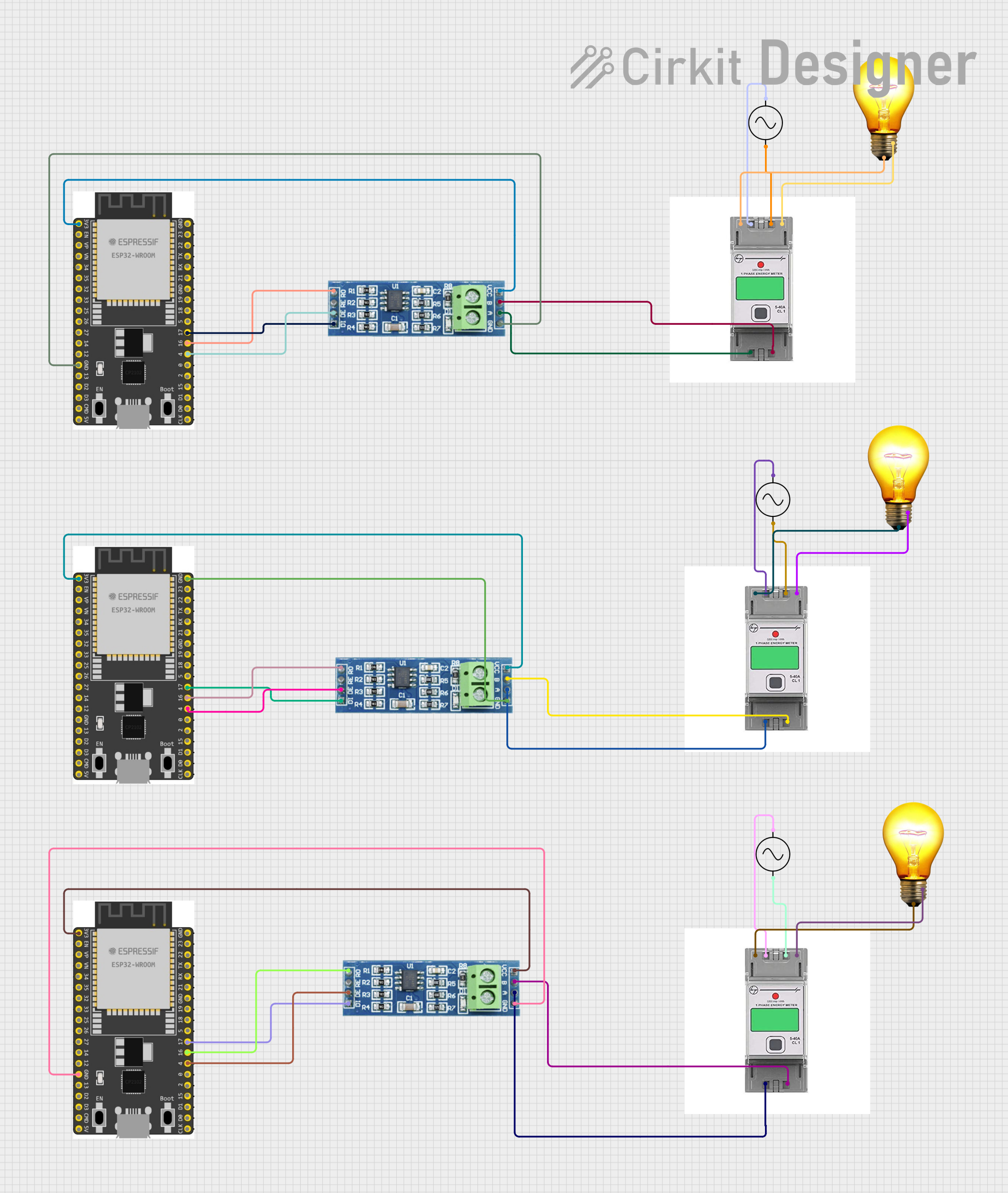
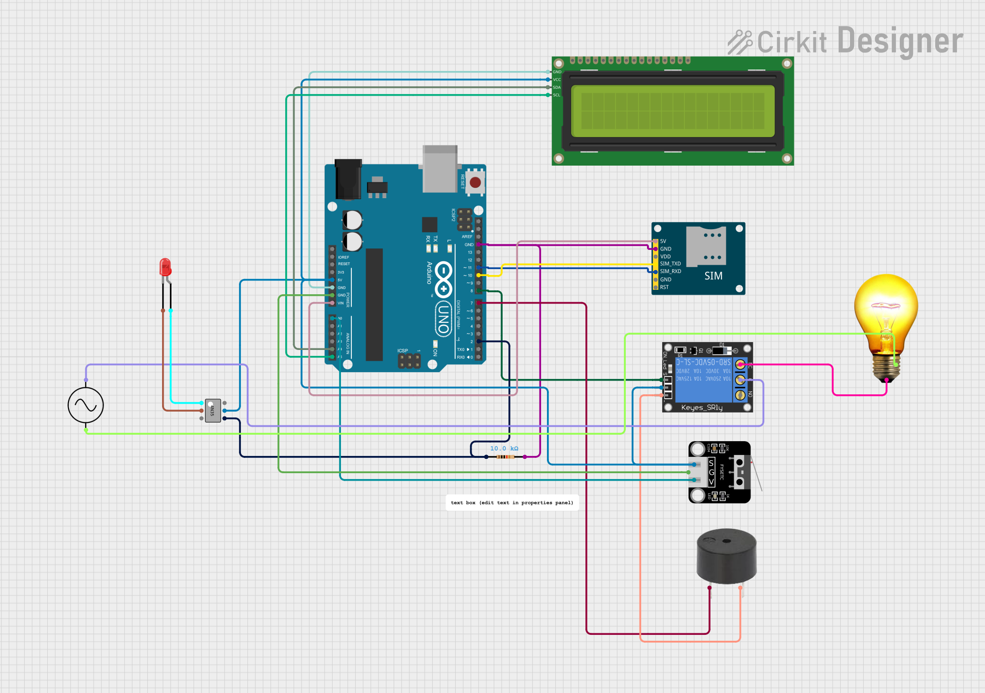
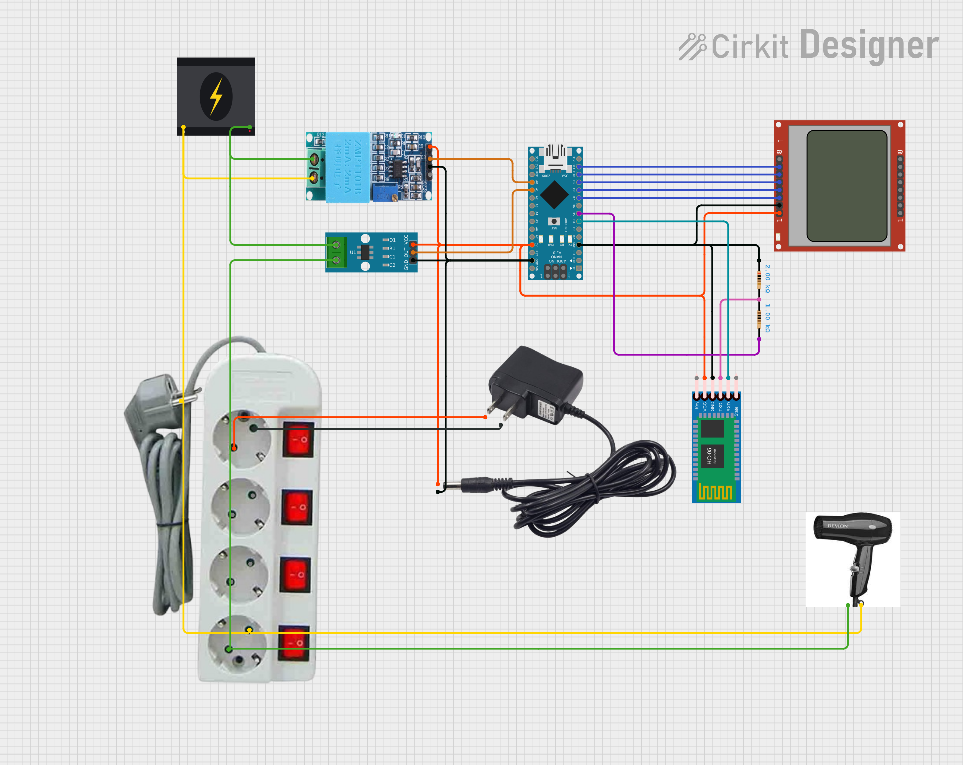
Explore Projects Built with Wattmeter
Common Applications:
- Monitoring power consumption in household or industrial appliances.
- Measuring power output in renewable energy systems (e.g., solar panels, wind turbines).
- Testing and troubleshooting electrical circuits.
- Evaluating the efficiency of electrical devices.
Technical Specifications
Below are the general technical specifications for a typical digital wattmeter. Specifications may vary depending on the model and manufacturer.
Key Technical Details:
- Input Voltage Range: 0V to 300V AC/DC (model-dependent)
- Input Current Range: 0A to 20A (model-dependent)
- Power Measurement Range: 0W to 6000W
- Accuracy: ±1% of reading
- Display Type: LCD or LED
- Power Supply: Internal battery or external power source (e.g., USB or mains)
- Communication Interface (optional): UART, I2C, or RS485 for data logging
- Operating Temperature: -10°C to 50°C
- Dimensions: Varies by model (e.g., 100mm x 50mm x 30mm)
Pin Configuration and Descriptions:
For wattmeters with external connections, the pin configuration typically includes terminals for voltage and current inputs. Below is an example configuration:
| Pin/Terminal | Label | Description |
|---|---|---|
| 1 | V+ | Positive voltage input terminal (connect to the live wire in AC systems). |
| 2 | V- | Negative voltage input terminal (connect to the neutral wire in AC systems). |
| 3 | I+ | Positive current input terminal (connect to the load side of the circuit). |
| 4 | I- | Negative current input terminal (connect to the return path of the circuit). |
| 5 (optional) | GND | Ground terminal for external communication or power supply. |
| 6 (optional) | TX/RX | Communication pins for UART or other interfaces (used for data logging). |
Usage Instructions
How to Use the Wattmeter in a Circuit:
Connect the Voltage Terminals:
- Attach the V+ terminal to the live wire of the circuit.
- Attach the V- terminal to the neutral wire of the circuit.
- Ensure the voltage input does not exceed the wattmeter's rated voltage range.
Connect the Current Terminals:
- Pass the load current through the I+ and I- terminals.
- Ensure the current input does not exceed the wattmeter's rated current range.
Power the Wattmeter:
- If the wattmeter requires an external power source, connect it to the appropriate terminals (e.g., USB or GND).
Read the Display:
- The wattmeter will display the power consumption or generation in watts.
- Some models may also display voltage, current, and power factor.
Optional Data Logging:
- If the wattmeter supports communication interfaces (e.g., UART), connect it to a microcontroller or computer for data logging.
Important Considerations:
- Always ensure the wattmeter's voltage and current ratings match the circuit's specifications.
- Use proper insulation and safety precautions when working with high-voltage circuits.
- For AC circuits, ensure the wattmeter is designed to handle the frequency (e.g., 50Hz or 60Hz).
- Avoid overloading the wattmeter, as this may damage the device or cause inaccurate readings.
Example: Connecting a Wattmeter to an Arduino UNO
If the wattmeter supports UART communication, you can connect it to an Arduino UNO for data logging. Below is an example code snippet:
#include <SoftwareSerial.h>

// Define RX and TX pins for communication with the wattmeter
SoftwareSerial wattmeterSerial(10, 11); // RX = pin 10, TX = pin 11

void setup() {
  Serial.begin(9600); // Initialize serial monitor
  wattmeterSerial.begin(9600); // Initialize wattmeter communication

  Serial.println("Wattmeter Data Logging Started");
}

void loop() {
  // Check if data is available from the wattmeter
  if (wattmeterSerial.available()) {
    String wattmeterData = ""; // Variable to store wattmeter data

    // Read data from the wattmeter
    while (wattmeterSerial.available()) {
      char c = wattmeterSerial.read();
      wattmeterData += c;
    }

    // Print the wattmeter data to the serial monitor
    Serial.println("Wattmeter Reading: " + wattmeterData);
  }

  delay(1000); // Wait for 1 second before the next reading
}
Note: Ensure the wattmeter's communication protocol and baud rate match the Arduino settings.
Troubleshooting and FAQs
Common Issues:
No Display or Readings:
- Cause: Incorrect wiring or insufficient power supply.
- Solution: Double-check all connections and ensure the wattmeter is powered correctly.
Inaccurate Readings:
- Cause: Exceeding the wattmeter's voltage or current range.
- Solution: Verify that the circuit's voltage and current are within the wattmeter's specifications.
Communication Errors with Arduino:
- Cause: Incorrect baud rate or wiring.
- Solution: Ensure the baud rate in the Arduino code matches the wattmeter's settings. Check the RX/TX connections.
Overheating:
- Cause: Prolonged use at maximum rated current.
- Solution: Reduce the load or use a wattmeter with a higher current rating.
FAQs:
Q: Can I use a wattmeter for DC circuits?
A: Yes, but ensure the wattmeter is designed to handle DC voltage and current.Q: How do I measure power factor with a wattmeter?
A: Some advanced wattmeters display power factor directly. For others, you may need to calculate it using voltage, current, and power readings.Q: Can I use a wattmeter with a solar panel?
A: Yes, as long as the wattmeter's voltage and current ratings are compatible with the solar panel's output.Q: Is it safe to use a wattmeter with high-voltage circuits?
A: Yes, but always follow proper safety precautions and use a wattmeter rated for the voltage level.
By following this documentation, you can effectively use a wattmeter to measure and monitor electrical power in various applications.