How to Use ESP32 A1S: Examples, Pinouts, and Specs
Introduction
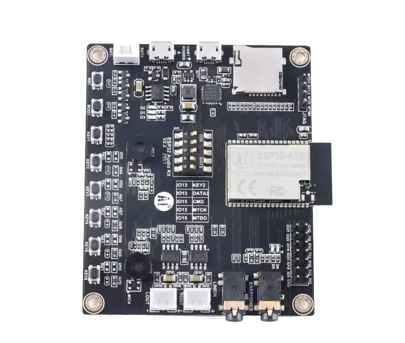
The ESP32 A1S Audio Kit, manufactured by ESP32, is a highly versatile Wi-Fi and Bluetooth module designed for IoT applications. It features a powerful dual-core processor, integrated audio capabilities, and support for various communication protocols. This module is particularly well-suited for smart devices, audio processing, and embedded systems requiring wireless connectivity and audio functionality.
Explore Projects Built with ESP32 A1S
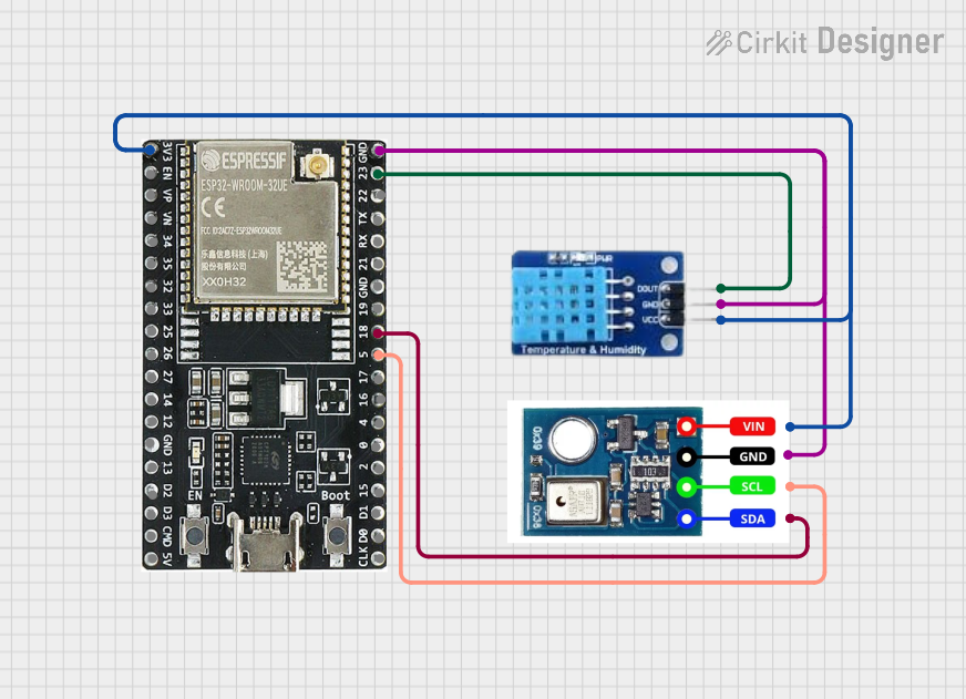

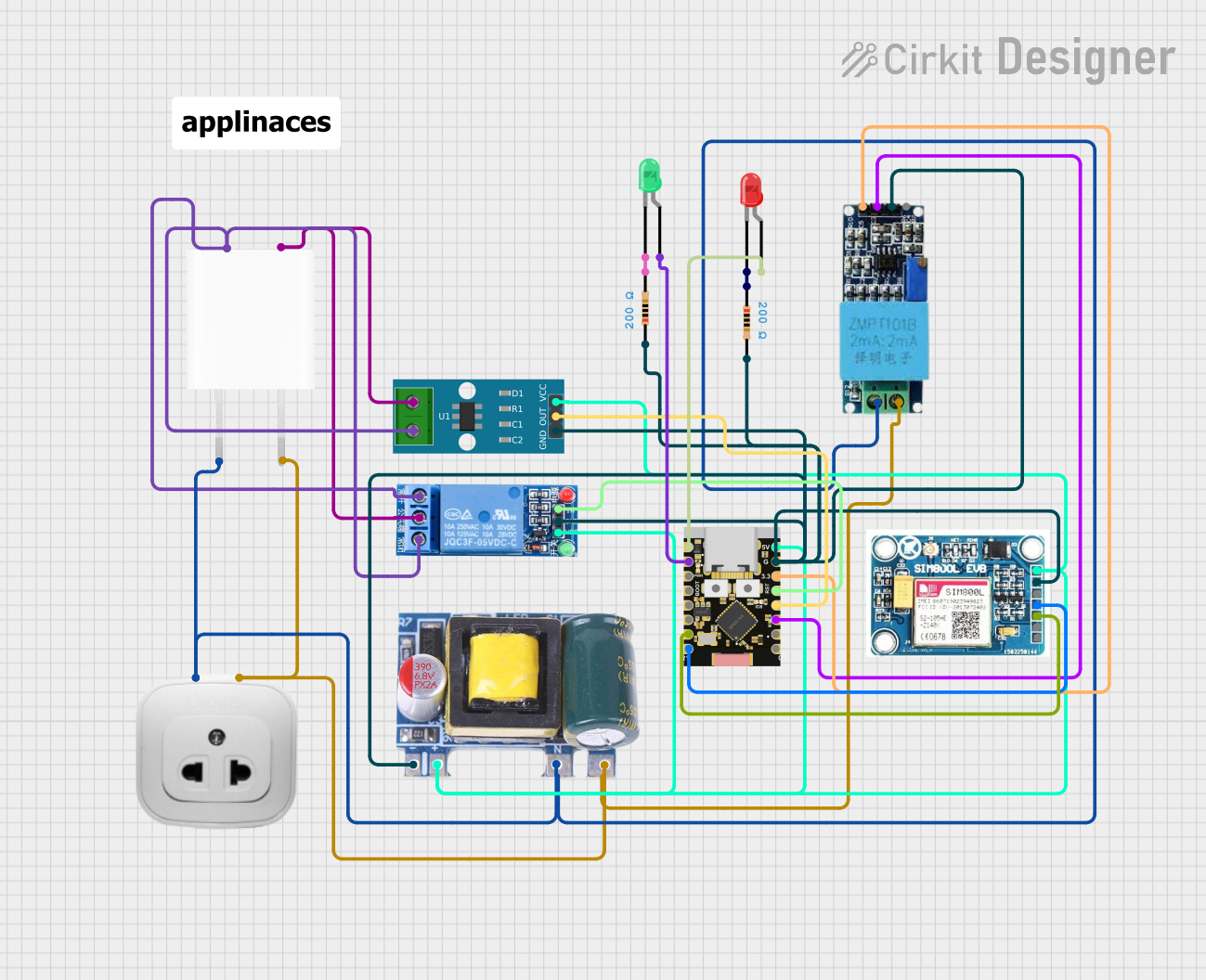

Explore Projects Built with ESP32 A1S
Common Applications
- Smart speakers and voice assistants
- IoT-enabled audio devices
- Wireless audio streaming systems
- Home automation and smart home hubs
- Embedded systems with audio processing requirements
Technical Specifications
Key Technical Details
| Parameter | Specification |
|---|---|
| Processor | Dual-core Xtensa® 32-bit LX6 CPU |
| Clock Speed | Up to 240 MHz |
| Wireless Connectivity | Wi-Fi 802.11 b/g/n, Bluetooth 4.2 BR/EDR and BLE |
| Flash Memory | 4 MB (expandable) |
| RAM | 520 KB SRAM |
| Audio Codec | ES8388 (integrated) |
| Audio Output | Stereo output, headphone jack, and speaker pins |
| GPIO Pins | 32 (configurable for various peripherals) |
| Operating Voltage | 3.3V |
| Power Consumption | Ultra-low power modes available |
| Dimensions | 50 mm x 50 mm |
Pin Configuration and Descriptions
The ESP32 A1S Audio Kit features a variety of pins for audio, power, and general-purpose input/output (GPIO). Below is a summary of the key pin configurations:
Power and Ground Pins
| Pin Name | Description |
|---|---|
| 3V3 | 3.3V power input |
| GND | Ground connection |
Audio Interface Pins
| Pin Name | Description |
|---|---|
| LOUT | Left audio output |
| ROUT | Right audio output |
| MIC_IN | Microphone input |
| SPK+ | Speaker positive terminal |
| SPK- | Speaker negative terminal |
GPIO and Communication Pins
| Pin Name | Description |
|---|---|
| GPIO0 | General-purpose I/O, boot mode selection |
| GPIO2 | General-purpose I/O |
| GPIO5 | General-purpose I/O |
| TXD0 | UART0 transmit |
| RXD0 | UART0 receive |
| I2C_SCL | I2C clock line |
| I2C_SDA | I2C data line |
Usage Instructions
How to Use the ESP32 A1S in a Circuit
- Power Supply: Connect the 3V3 pin to a 3.3V power source and GND to ground.
- Audio Connections:
- For stereo output, connect the LOUT and ROUT pins to an audio amplifier or headphones.
- For microphone input, connect a compatible microphone to the MIC_IN pin.
- For speaker output, connect SPK+ and SPK- to a speaker.
- GPIO Configuration: Use the GPIO pins for interfacing with sensors, actuators, or other peripherals.
- Programming: The ESP32 A1S can be programmed using the Arduino IDE or ESP-IDF (Espressif IoT Development Framework).
Important Considerations
- Ensure the power supply is stable and within the 3.3V range to avoid damaging the module.
- Use appropriate pull-up or pull-down resistors for GPIO pins as needed.
- When using the audio codec, configure the ES8388 settings correctly in your software.
- Avoid connecting high-current devices directly to GPIO pins without proper interfacing.
Example Code for Arduino IDE
Below is an example of how to initialize the ESP32 A1S for audio playback using the I2S protocol:
#include <Arduino.h>
#include <driver/i2s.h>

// I2S configuration for audio playback
void setupI2S() {
  i2s_config_t i2s_config = {
    .mode = (i2s_mode_t)(I2S_MODE_MASTER | I2S_MODE_TX), // Master mode, transmit only
    .sample_rate = 44100,                               // Audio sample rate
    .bits_per_sample = I2S_BITS_PER_SAMPLE_16BIT,       // 16-bit audio
    .channel_format = I2S_CHANNEL_FMT_RIGHT_LEFT,       // Stereo format
    .communication_format = I2S_COMM_FORMAT_I2S,        // I2S communication format
    .intr_alloc_flags = 0,                              // Default interrupt allocation
    .dma_buf_count = 8,                                 // Number of DMA buffers
    .dma_buf_len = 64,                                  // Length of each DMA buffer
    .use_apll = false                                   // Disable APLL
  };

  // Pin configuration for I2S
  i2s_pin_config_t pin_config = {
    .bck_io_num = 26,   // Bit clock pin
    .ws_io_num = 25,    // Word select pin
    .data_out_num = 22, // Data output pin
    .data_in_num = -1   // Not used
  };

  // Install and start I2S driver
  i2s_driver_install(I2S_NUM_0, &i2s_config, 0, NULL);
  i2s_set_pin(I2S_NUM_0, &pin_config);
}

void setup() {
  Serial.begin(115200);
  setupI2S(); // Initialize I2S for audio playback
  Serial.println("I2S setup complete.");
}

void loop() {
  // Audio playback logic goes here
}
Troubleshooting and FAQs
Common Issues
No Audio Output:
- Ensure the audio codec (ES8388) is properly initialized in your software.
- Verify the connections to the LOUT and ROUT pins or speaker terminals.
- Check the I2S configuration for correct sample rate and bit depth.
Wi-Fi or Bluetooth Not Working:
- Confirm that the ESP32 A1S is within range of the Wi-Fi network or Bluetooth device.
- Ensure the firmware includes the necessary libraries for wireless communication.
Module Not Powering On:
- Verify the power supply voltage is 3.3V.
- Check for loose or incorrect connections to the 3V3 and GND pins.
Tips for Troubleshooting
- Use a multimeter to check voltage levels at the power and GPIO pins.
- Test the module with a simple program (e.g., blinking an LED) to confirm basic functionality.
- Refer to the ESP32 A1S datasheet for detailed hardware and software guidelines.
FAQs
Q: Can the ESP32 A1S be powered via USB?
A: No, the ESP32 A1S Audio Kit requires a 3.3V power supply connected to the 3V3 pin.
Q: Is the ESP32 A1S compatible with Arduino libraries?
A: Yes, the ESP32 A1S can be programmed using the Arduino IDE and supports many Arduino libraries.
Q: How do I update the firmware on the ESP32 A1S?
A: Firmware can be updated via the UART interface using tools like the ESP32 Flash Download Tool or via OTA (Over-The-Air) updates.
Q: Can I use the ESP32 A1S for real-time audio processing?
A: Yes, the dual-core processor and integrated audio codec make it suitable for real-time audio applications.