How to Use DIP Switch (8 Position): Examples, Pinouts, and Specs
Introduction
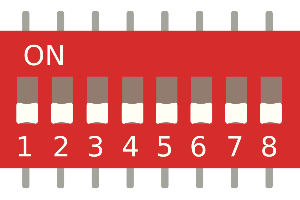
A DIP switch (Dual In-line Package switch) is a manual electric switch that is used to configure settings or select options on a circuit board. The 8-position variant features 8 individual switches that can be toggled on or off independently. This component is widely used in various applications, including:
- Setting hardware configurations
- Selecting operational modes
- Enabling or disabling features
- Address selection in communication protocols
Explore Projects Built with DIP Switch (8 Position)
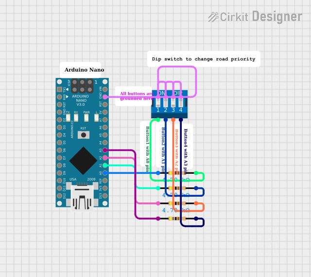
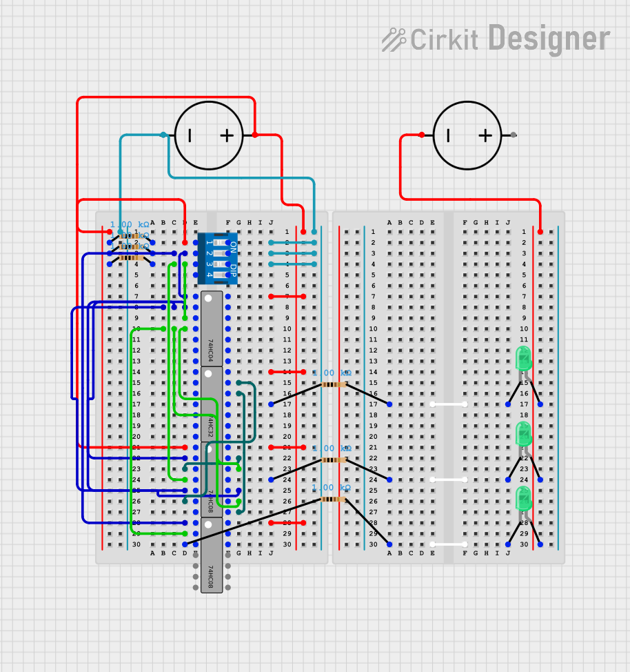

Explore Projects Built with DIP Switch (8 Position)
Technical Specifications
Key Technical Details
| Parameter | Value |
|---|---|
| Number of Switches | 8 |
| Contact Rating | 25 mA at 24 VDC |
| Insulation Resistance | 100 MΩ min at 500 VDC |
| Dielectric Strength | 500 VAC for 1 minute |
| Operating Temperature | -20°C to +70°C |
| Actuator Type | Slide |
| Mounting Type | Through Hole |
Pin Configuration and Descriptions
| Pin Number | Description |
|---|---|
| 1 | Switch 1 Output |
| 2 | Switch 2 Output |
| 3 | Switch 3 Output |
| 4 | Switch 4 Output |
| 5 | Switch 5 Output |
| 6 | Switch 6 Output |
| 7 | Switch 7 Output |
| 8 | Switch 8 Output |
| 9 | Common Ground (GND) |
| 10 | Common Ground (GND) |
Usage Instructions
How to Use the Component in a Circuit
Mounting the DIP Switch:
- Insert the DIP switch into the through-hole slots on the PCB.
- Ensure that the orientation is correct, with the actuator side facing up.
- Solder the pins to secure the switch in place.
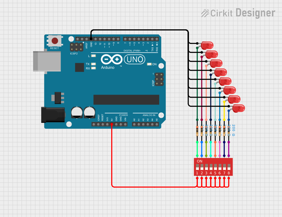
Connecting to a Microcontroller (e.g., Arduino UNO):
- Connect each switch output pin (1-8) to a digital input pin on the Arduino.
- Connect one of the common ground pins (9 or 10) to the GND pin on the Arduino.
Example Circuit Diagram
DIP Switch Pin 1 -> Arduino Digital Pin 2
DIP Switch Pin 2 -> Arduino Digital Pin 3
DIP Switch Pin 3 -> Arduino Digital Pin 4
DIP Switch Pin 4 -> Arduino Digital Pin 5
DIP Switch Pin 5 -> Arduino Digital Pin 6
DIP Switch Pin 6 -> Arduino Digital Pin 7
DIP Switch Pin 7 -> Arduino Digital Pin 8
DIP Switch Pin 8 -> Arduino Digital Pin 9
DIP Switch GND  -> Arduino GND
Example Arduino Code
// Define the DIP switch pins
const int dipPins[8] = {2, 3, 4, 5, 6, 7, 8, 9};

void setup() {
  // Initialize serial communication
  Serial.begin(9600);

  // Set DIP switch pins as input
  for (int i = 0; i < 8; i++) {
    pinMode(dipPins[i], INPUT);
  }
}

void loop() {
  // Read and print the state of each DIP switch
  for (int i = 0; i < 8; i++) {
    int state = digitalRead(dipPins[i]);
    Serial.print("Switch ");
    Serial.print(i + 1);
    Serial.print(": ");
    Serial.println(state ? "ON" : "OFF");
  }

  // Add a small delay to avoid flooding the serial monitor
  delay(500);
}
Important Considerations and Best Practices
- Debouncing: Mechanical switches can produce noise or "bounce" when toggled. Consider implementing software debouncing to ensure stable readings.
- Current Limiting: Ensure that the current through each switch does not exceed the contact rating (25 mA) to avoid damage.
- Proper Grounding: Connect the common ground pins to the ground of your circuit to ensure proper operation.
Troubleshooting and FAQs
Common Issues Users Might Face
Unstable Readings:
- Solution: Implement software debouncing to filter out noise from the switch toggling.
Switch Not Responding:
- Solution: Check the solder joints and ensure that the switch is properly connected to the circuit.
Incorrect Pin Mapping:
- Solution: Verify the pin connections between the DIP switch and the microcontroller.
FAQs
Q1: Can I use the DIP switch for high voltage applications?
- A1: No, the DIP switch is rated for low voltage applications (up to 24 VDC). Using it for high voltage applications can damage the switch and pose safety risks.
Q2: How do I implement software debouncing?
- A2: You can implement software debouncing by adding a small delay after reading the switch state and checking if the state remains consistent. Alternatively, you can use debouncing libraries available for Arduino.
Q3: Can I use fewer than 8 switches?
- A3: Yes, you can use any number of switches from the 8 available. Simply connect the switches you need and leave the others unconnected.
By following this documentation, you should be able to effectively use the 8-position DIP switch in your projects. Whether you are a beginner or an experienced user, this guide provides the necessary information to get started and troubleshoot common issues.