How to Use L293D_MOTOR_DRIVER: Examples, Pinouts, and Specs
Introduction
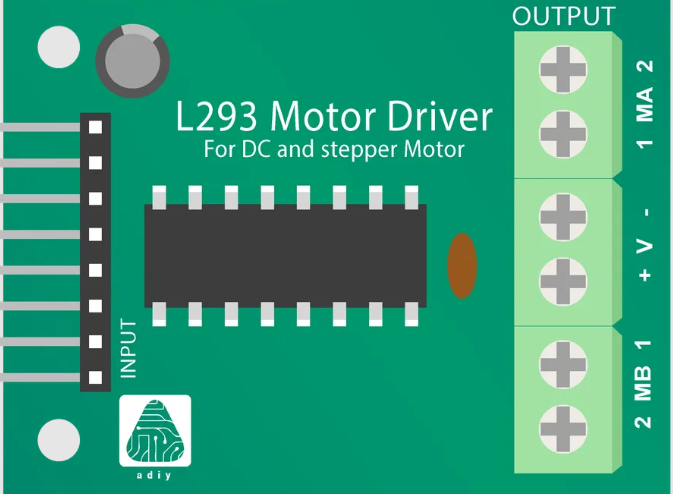
The L293D Motor Driver is an integrated circuit designed to control the direction and speed of DC motors. It is capable of driving two motors simultaneously in both forward and reverse directions. The L293D is widely used in robotics, automation projects, and any application requiring bidirectional control of DC motors.
Explore Projects Built with L293D_MOTOR_DRIVER

Explore Projects Built with L293D_MOTOR_DRIVER
Common Applications and Use Cases
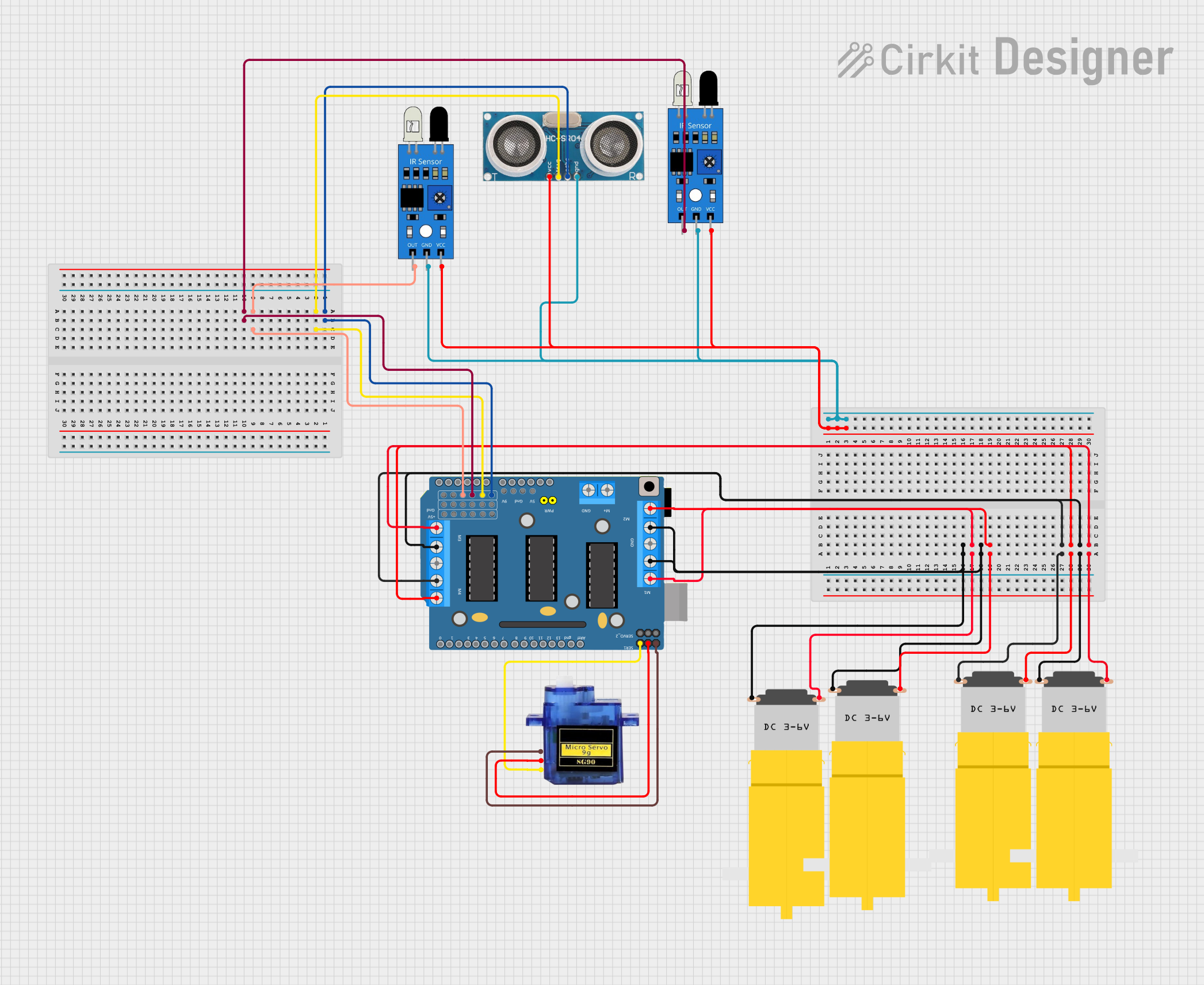
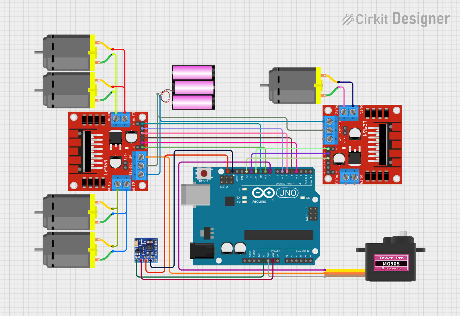
- Robotics
- Automated Guided Vehicles (AGVs)
- Home automation systems
- Hobbyist projects involving motor control
Technical Specifications
Key Technical Details
- Supply Voltage (Vcc1): 4.5V to 36V
- Logic Supply Voltage (Vcc2): 4.5V to 7V
- Output Current (each channel): 600mA
- Peak Output Current (each channel): 1.2A
- Enable Input Voltage: 4.5V to 7V
- Internal Clamp Diodes: For inductive transient suppression
Pin Configuration and Descriptions
| Pin Number | Name | Description |
|---|---|---|
| 1 | Enable 1,2 | Enables motor driver channels 1 and 2 |
| 2 | Input 1 | Logic input for motor channel 1 |
| 3 | Output 1 | Output to motor channel 1 |
| 4, 5 | Ground | Ground pins |
| 6 | Output 2 | Output to motor channel 2 |
| 7 | Input 2 | Logic input for motor channel 2 |
| 8 | Vcc2 | Logic supply voltage |
| 9 | Enable 3,4 | Enables motor driver channels 3 and 4 |
| 10 | Input 3 | Logic input for motor channel 3 |
| 11 | Output 3 | Output to motor channel 3 |
| 12, 13 | Ground | Ground pins |
| 14 | Output 4 | Output to motor channel 4 |
| 15 | Input 4 | Logic input for motor channel 4 |
| 16 | Vcc1 | Motor supply voltage |
Usage Instructions
How to Use the Component in a Circuit
- Connect the motor supply voltage (Vcc1) to pin 16, and the logic supply voltage (Vcc2) to pin 8.
- Connect the ground pins (4, 5, 12, 13) to the common ground of the power supply and the control logic.
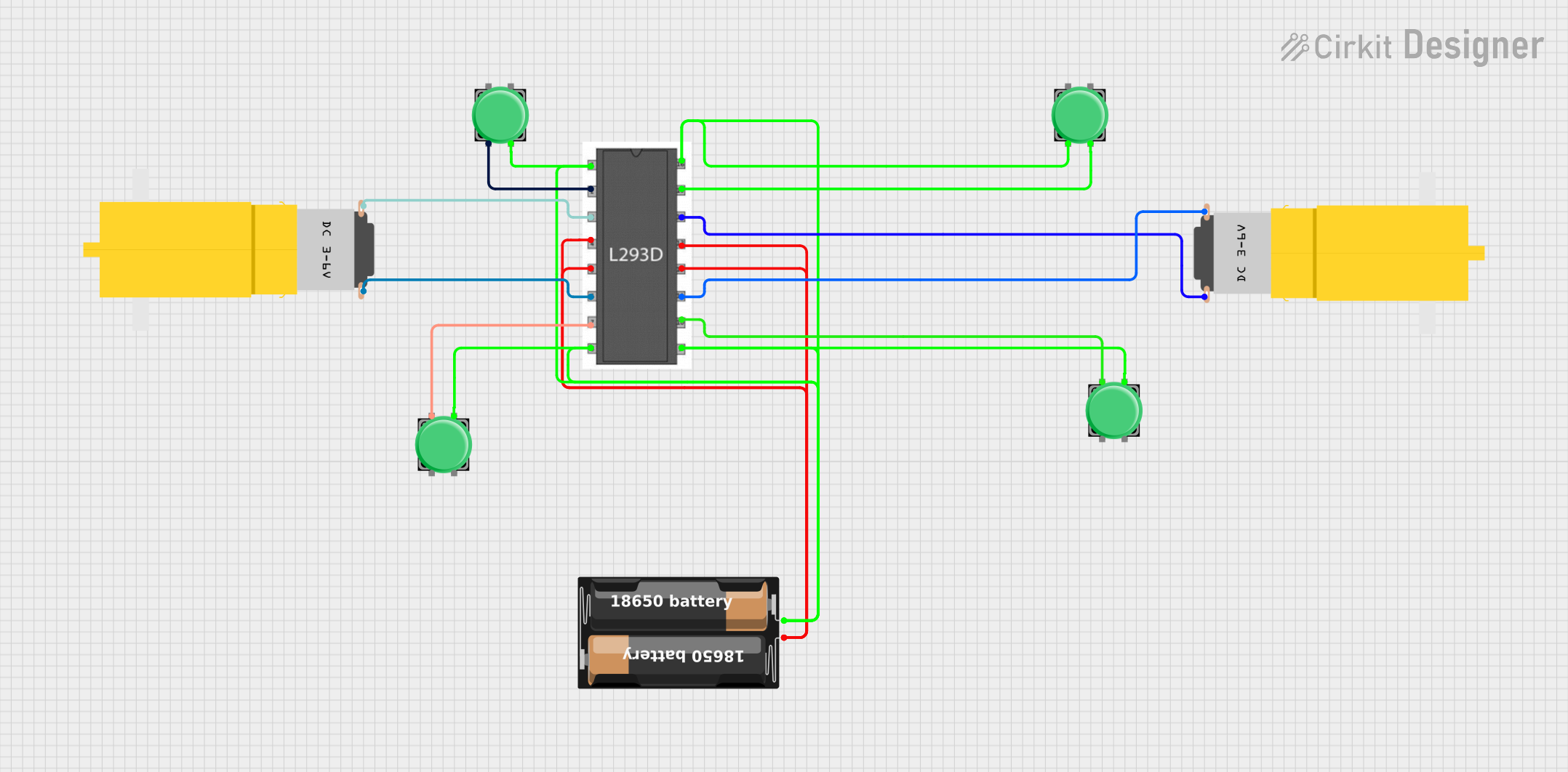
- Connect the motors to the output pins (3, 6 for one motor; 11, 14 for the other motor).
- Apply logic signals to the input pins (2, 7 for one motor; 10, 15 for the other motor) to control the direction of the motors.
- Use the enable pins (1, 9) to enable or disable the motor channels.
Important Considerations and Best Practices
- Ensure that the power supply can deliver sufficient current for the motors.
- Use external heat sinks if operating near the peak output current to prevent overheating.
- Connect diodes externally if using inductive loads to protect against voltage spikes.
- Avoid applying signals to the input pins when the enable pins are low to prevent damage.
Example Code for Arduino UNO
// Define the L293D connections to the Arduino
const int motorPin1 = 3; // Input 1
const int motorPin2 = 4; // Input 2
const int enablePin = 9; // Enable 1,2

void setup() {
  // Set motor control pins as outputs
  pinMode(motorPin1, OUTPUT);
  pinMode(motorPin2, OUTPUT);
  pinMode(enablePin, OUTPUT);

  // Start with the motor disabled
  digitalWrite(enablePin, LOW);
}

void loop() {
  // Enable the motor
  digitalWrite(enablePin, HIGH);

  // Spin the motor in one direction
  digitalWrite(motorPin1, HIGH);
  digitalWrite(motorPin2, LOW);
  delay(2000); // Run for 2 seconds

  // Stop the motor
  digitalWrite(enablePin, LOW);
  delay(1000); // Wait for 1 second

  // Spin the motor in the opposite direction
  digitalWrite(enablePin, HIGH);
  digitalWrite(motorPin1, LOW);
  digitalWrite(motorPin2, HIGH);
  delay(2000); // Run for 2 seconds

  // Stop the motor
  digitalWrite(enablePin, LOW);
  delay(1000); // Wait for 1 second
}
Troubleshooting and FAQs
Common Issues Users Might Face
- Motor not running: Check power supply connections, ensure enable pin is high.
- Motor running weakly: Verify that the power supply can deliver enough current.
- Overheating: Attach heat sinks or reduce the load on the motor.
Solutions and Tips for Troubleshooting
- Double-check wiring against the pin configuration table.
- Use a multimeter to verify the presence of supply voltage at the motor driver.
- Ensure that the logic inputs are receiving the correct signals from the control source.
FAQs
Q: Can the L293D drive stepper motors? A: Yes, the L293D can drive bipolar stepper motors with proper control signals.
Q: What is the function of the enable pins? A: The enable pins allow the corresponding motor channels to be turned on or off.
Q: Can I use the L293D without an external heat sink? A: Yes, for low current applications. However, for currents approaching the peak output, a heat sink is recommended.
Q: How do I control the speed of the motors? A: Speed control can be achieved by applying PWM signals to the enable pins.
Q: Is it necessary to use external diodes with the L293D? A: The L293D has built-in clamp diodes for inductive load applications, but external diodes can be added for extra protection.