How to Use ME702 ADC: Examples, Pinouts, and Specs
Introduction
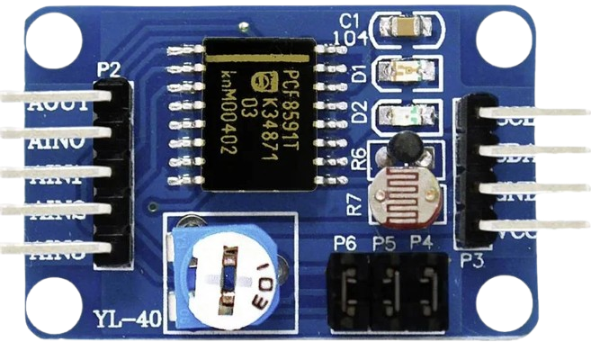
The ME702 ADC, manufactured by Iduino (Part ID: RS232), is a high-performance analog-to-digital converter (ADC) designed for precise signal conversion. It supports multiple input channels, high sampling rates, and low power consumption, making it ideal for applications requiring accurate data acquisition and signal processing.
Explore Projects Built with ME702 ADC


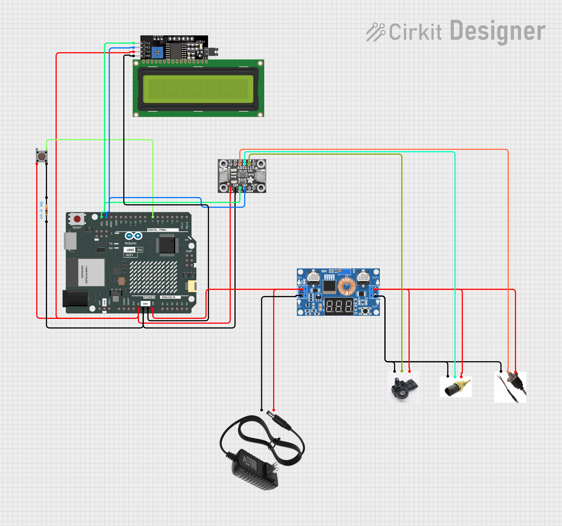
Explore Projects Built with ME702 ADC
Common Applications and Use Cases
- Data acquisition systems
- Signal processing in industrial automation
- Medical instrumentation
- Audio signal conversion
- IoT devices and embedded systems
Technical Specifications
The ME702 ADC is designed to deliver reliable performance in a wide range of applications. Below are its key technical specifications:
General Specifications
| Parameter | Value |
|---|---|
| Manufacturer | Iduino |
| Part ID | RS232 |
| Resolution | 12-bit |
| Number of Channels | 8 |
| Sampling Rate | Up to 200 kSPS (kilo-samples per second) |
| Input Voltage Range | 0–5V |
| Power Supply Voltage | 3.3V or 5V |
| Power Consumption | < 10 mW |
| Communication Interface | SPI |
| Operating Temperature | -40°C to 85°C |
Pin Configuration and Descriptions
The ME702 ADC comes in a 16-pin package. Below is the pin configuration:
| Pin Number | Pin Name | Description |
|---|---|---|
| 1 | VDD | Power supply (3.3V or 5V) |
| 2 | GND | Ground |
| 3 | CS | Chip Select (active low) |
| 4 | SCLK | Serial Clock input for SPI |
| 5 | MOSI | Master Out Slave In (data input to ADC) |
| 6 | MISO | Master In Slave Out (data output from ADC) |
| 7–14 | CH0–CH7 | Analog input channels (CH0 to CH7) |
| 15 | REF+ | Positive reference voltage input |
| 16 | REF- | Negative reference voltage input |
Usage Instructions
The ME702 ADC is straightforward to integrate into circuits, especially for microcontroller-based systems like Arduino. Below are the steps and considerations for using the component:
Connecting the ME702 ADC
- Power Supply: Connect the VDD pin to a 3.3V or 5V power source and the GND pin to ground.
- SPI Interface: Connect the SPI pins (CS, SCLK, MOSI, and MISO) to the corresponding SPI pins on your microcontroller.
- Analog Inputs: Connect the analog signals to the input channels (CH0–CH7). Ensure the input voltage does not exceed the specified range (0–5V).
- Reference Voltage: Provide a stable reference voltage to the REF+ and REF- pins. Typically, REF+ is connected to VDD, and REF- is connected to GND.
Arduino UNO Example Code
Below is an example of how to interface the ME702 ADC with an Arduino UNO using the SPI library:
#include <SPI.h>

// Define SPI pins for the ME702 ADC
const int CS_PIN = 10; // Chip Select pin

void setup() {
  // Initialize SPI communication
  SPI.begin();
  pinMode(CS_PIN, OUTPUT);
  digitalWrite(CS_PIN, HIGH); // Set CS pin to HIGH (inactive)

  Serial.begin(9600); // Initialize serial communication for debugging
}

uint16_t readADC(uint8_t channel) {
  // Ensure the channel is within the valid range (0–7)
  if (channel > 7) return 0;

  // Build the command byte (start bit + single-ended mode + channel selection)
  uint8_t command = 0b11000000 | (channel << 3);

  // Start SPI communication
  digitalWrite(CS_PIN, LOW);

  // Send the command and read the response
  SPI.transfer(command); // Send the command byte
  uint8_t highByte = SPI.transfer(0x00); // Read the high byte of the result
  uint8_t lowByte = SPI.transfer(0x00);  // Read the low byte of the result

  // End SPI communication
  digitalWrite(CS_PIN, HIGH);

  // Combine the high and low bytes into a 12-bit result
  uint16_t result = ((highByte & 0x0F) << 8) | lowByte;

  return result;
}

void loop() {
  // Read from channel 0
  uint16_t adcValue = readADC(0);

  // Print the ADC value to the serial monitor
  Serial.print("ADC Value: ");
  Serial.println(adcValue);

  delay(500); // Wait for 500ms before the next reading
}
Important Considerations
- Input Voltage Range: Ensure the input signals are within the 0–5V range to avoid damaging the ADC.
- Reference Voltage: Use a stable reference voltage for accurate conversions.
- Sampling Rate: Adjust the SPI clock speed to match the desired sampling rate, ensuring it does not exceed the ADC's maximum rate of 200 kSPS.
- Noise Reduction: Use proper grounding and decoupling capacitors to minimize noise in the circuit.
Troubleshooting and FAQs
Common Issues and Solutions
No Output or Incorrect Readings
- Cause: Incorrect SPI connections or configuration.
- Solution: Verify the SPI connections (CS, SCLK, MOSI, MISO) and ensure the SPI settings (clock polarity, phase, and speed) match the ADC's requirements.
Fluctuating ADC Values
- Cause: Noise in the analog input or unstable reference voltage.
- Solution: Use decoupling capacitors near the power supply and reference voltage pins. Shield analog input lines from noise sources.
Overvoltage on Input Channels
- Cause: Input voltage exceeds the 0–5V range.
- Solution: Use voltage dividers or level shifters to ensure input signals are within the specified range.
Low Sampling Rate
- Cause: SPI clock speed is too low.
- Solution: Increase the SPI clock speed, ensuring it does not exceed the ADC's maximum supported rate.
FAQs
Q: Can the ME702 ADC be used with 3.3V systems?
A: Yes, the ME702 ADC supports both 3.3V and 5V power supplies, making it compatible with a wide range of systems.
Q: How many channels can be used simultaneously?
A: The ME702 ADC has 8 input channels, but only one channel can be read at a time. You can switch between channels programmatically.
Q: What is the maximum resolution of the ME702 ADC?
A: The ME702 ADC provides a 12-bit resolution, allowing for 4096 discrete levels of measurement.
Q: Is the ME702 ADC compatible with other microcontrollers besides Arduino?
A: Yes, the ME702 ADC can be used with any microcontroller that supports SPI communication, such as STM32, ESP32, and Raspberry Pi.
By following this documentation, users can effectively integrate the ME702 ADC into their projects and achieve accurate analog-to-digital conversions.