How to Use E Stop: Examples, Pinouts, and Specs
Introduction
The E Stop, or Emergency Stop switch, is a safety device designed to immediately cut power to a machine or circuit in case of an emergency. It is a fail-safe control mechanism that ensures the safety of operators and equipment by halting operations instantly when activated. E Stops are commonly used in industrial machinery, robotics, and other systems where quick power disconnection is critical to prevent accidents or damage.
Explore Projects Built with E Stop


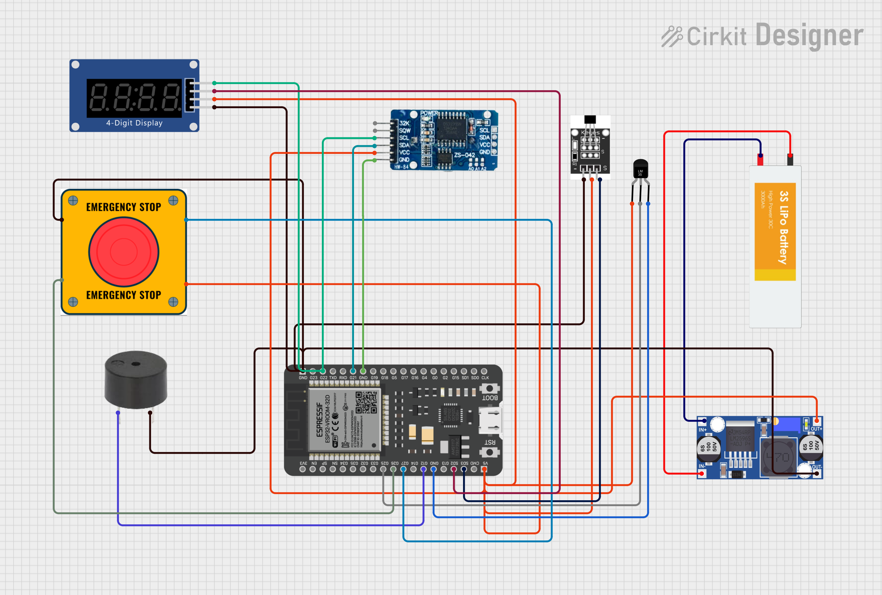

Explore Projects Built with E Stop
Common Applications and Use Cases
- Industrial machinery and manufacturing equipment
- Robotics and automated systems
- Conveyor belts and assembly lines
- Laboratory equipment
- Emergency shutdown systems in hazardous environments
Technical Specifications
Key Technical Details
| Parameter | Value |
|---|---|
| Operating Voltage | 12V to 240V AC/DC |
| Current Rating | 10A (typical) |
| Contact Configuration | Normally Closed (NC) and Normally Open (NO) |
| Actuation Force | 22-30 N (typical) |
| Reset Mechanism | Twist-to-release or pull-to-release |
| Mounting Hole Diameter | 22mm or 30mm (depending on model) |
| Operating Temperature | -25°C to +55°C |
| IP Rating | IP65 (dust-tight and water-resistant) |
Pin Configuration and Descriptions
| Pin Label | Description |
|---|---|
| NC | Normally Closed contact; opens when the switch is pressed. |
| NO | Normally Open contact; closes when the switch is pressed. |
| COM | Common terminal; connects to the circuit. |
Usage Instructions
How to Use the E Stop in a Circuit
Wiring the E Stop:
- Connect the
COMterminal to the power source or control circuit. - For a Normally Closed (NC) configuration, connect the
NCterminal to the load or control input. This ensures the circuit is complete during normal operation and breaks when the E Stop is pressed. - For a Normally Open (NO) configuration, connect the
NOterminal to the load or control input. This configuration is used for triggering alarms or secondary actions when the E Stop is pressed.
- Connect the
Mounting the E Stop:
- Drill a hole in the control panel with a diameter matching the E Stop's mounting size (e.g., 22mm or 30mm).
- Secure the switch using the provided locking nut and ensure it is firmly in place.
Testing the E Stop:
- After installation, press the E Stop to verify that it cuts power or triggers the desired action.
- Reset the switch by twisting or pulling it, depending on the model, and ensure the circuit resumes normal operation.
Important Considerations and Best Practices
- Always ensure the E Stop is easily accessible and visible to operators.
- Use appropriate wire gauges and connectors to handle the current rating of the switch.
- Regularly inspect and test the E Stop to ensure it functions correctly.
- Do not bypass or disable the E Stop, as it is a critical safety feature.
- If using the E Stop with an Arduino or microcontroller, ensure the switch is properly debounced in the code to avoid false triggers.
Example: Connecting an E Stop to an Arduino UNO
The following example demonstrates how to use an E Stop with an Arduino UNO to control an LED. When the E Stop is pressed, the LED turns off.
// Define pin connections
const int eStopPin = 2;  // E Stop connected to digital pin 2
const int ledPin = 13;   // LED connected to digital pin 13

void setup() {
  pinMode(eStopPin, INPUT_PULLUP); // Set E Stop pin as input with pull-up resistor
  pinMode(ledPin, OUTPUT);         // Set LED pin as output
  digitalWrite(ledPin, HIGH);      // Turn on the LED initially
}

void loop() {
  // Read the state of the E Stop
  int eStopState = digitalRead(eStopPin);

  if (eStopState == LOW) {
    // If E Stop is pressed (LOW), turn off the LED
    digitalWrite(ledPin, LOW);
  } else {
    // If E Stop is not pressed, keep the LED on
    digitalWrite(ledPin, HIGH);
  }
}
Note: The E Stop is connected to the Arduino's digital pin 2 with a Normally Closed (NC) configuration. When the switch is pressed, the circuit opens, and the pin reads LOW.
Troubleshooting and FAQs
Common Issues and Solutions
| Issue | Solution |
|---|---|
| E Stop does not cut power when pressed. | Verify the wiring and ensure the COM and NC terminals are correctly connected. |
| Circuit does not resume after resetting. | Check if the reset mechanism (twist or pull) is functioning properly. |
| Arduino does not detect E Stop activation. | Ensure the pin is configured as INPUT_PULLUP and the wiring is correct. |
| E Stop feels loose or wobbly. | Tighten the mounting nut and ensure the switch is securely installed. |
FAQs
Can I use the E Stop with both AC and DC circuits?
Yes, the E Stop is designed to work with both AC and DC circuits within its voltage and current ratings.What is the difference between NC and NO contacts?
- NC (Normally Closed): The circuit is complete during normal operation and opens when the switch is pressed.
- NO (Normally Open): The circuit is open during normal operation and closes when the switch is pressed.
How often should I test the E Stop?
It is recommended to test the E Stop at least once a month to ensure it functions correctly.Can I use the E Stop in outdoor environments?
Yes, if the E Stop has an IP65 or higher rating, it is suitable for outdoor use. Ensure proper sealing during installation.