How to Use LED Bi-Pin 3W 600K: Examples, Pinouts, and Specs
Introduction
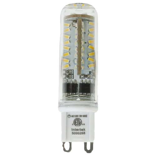
The LED Bi-Pin 3W 600K is a high-efficiency light-emitting diode (LED) with a bi-pin base. It is designed to operate at 3 watts of power and emits bright white light with a color temperature of 600K. This component is ideal for applications requiring energy-efficient and reliable lighting, such as residential, commercial, and decorative lighting systems.
Explore Projects Built with LED Bi-Pin 3W 600K

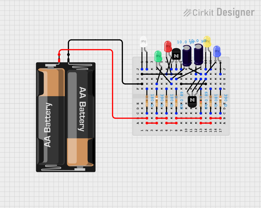

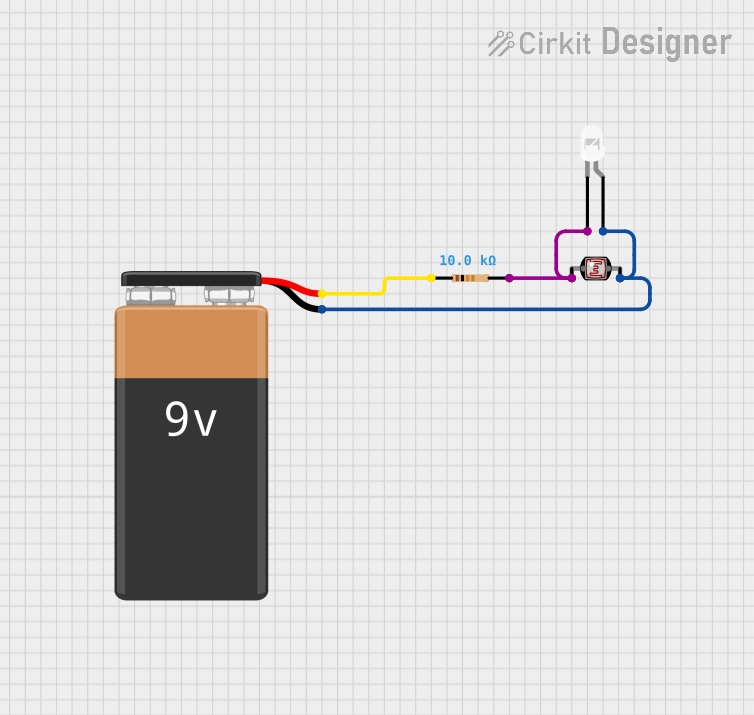
Explore Projects Built with LED Bi-Pin 3W 600K
Common Applications
- Accent lighting in homes and offices
- Task lighting for workspaces
- Decorative lighting in architectural designs
- Automotive interior and exterior lighting
- DIY electronics and hobby projects
Technical Specifications
Below are the key technical details for the LED Bi-Pin 3W 600K:
| Parameter | Value |
|---|---|
| Manufacturer | LED Bi-Pin 3W 600K |
| Manufacturer Part ID | LED Bi-Pin 3W 600K |
| Power Rating | 3 Watts |
| Color Temperature | 600K (Bright White) |
| Forward Voltage (Vf) | 3.0V - 3.4V |
| Forward Current (If) | 700mA |
| Luminous Flux | ~240 lumens |
| Beam Angle | 120° |
| Base Type | Bi-Pin |
| Operating Temperature | -20°C to +85°C |
| Lifespan | ~50,000 hours |
Pin Configuration
The LED Bi-Pin 3W 600K has a simple two-pin configuration:
| Pin | Description | Notes |
|---|---|---|
| Pin 1 | Anode (+) | Connect to the positive terminal of the power supply. |
| Pin 2 | Cathode (-) | Connect to the negative terminal of the power supply. |
Usage Instructions
How to Use the LED in a Circuit
- Power Supply: Ensure the power supply provides a forward voltage between 3.0V and 3.4V and a current of 700mA. Use a constant current driver for optimal performance and to prevent damage.
- Current Limiting Resistor: If connecting directly to a power source, calculate and use an appropriate resistor to limit the current. Use Ohm's Law:
[ R = \frac{V_{supply} - V_f}{I_f} ]
where ( V_{supply} ) is the supply voltage, ( V_f ) is the forward voltage, and ( I_f ) is the forward current. - Polarity: Connect the Anode (Pin 1) to the positive terminal and the Cathode (Pin 2) to the negative terminal of the power source.
- Heat Dissipation: Use a heat sink to manage heat dissipation, as the LED can become hot during operation.
Example: Connecting to an Arduino UNO
The LED Bi-Pin 3W 600K can be controlled using an Arduino UNO with a suitable transistor or MOSFET to handle the current. Below is an example circuit and code:
Circuit Setup
- Connect the Anode (Pin 1) of the LED to the collector of an NPN transistor (e.g., 2N2222).
- Connect the Cathode (Pin 2) to the ground (GND).
- Connect a 10kΩ resistor between the Arduino digital pin (e.g., D9) and the base of the transistor.
- Connect the emitter of the transistor to the ground.
- Use an external 3.3V power supply to power the LED, ensuring the current is limited.
Arduino Code
// Define the pin connected to the transistor base
const int ledPin = 9;

void setup() {
  pinMode(ledPin, OUTPUT); // Set pin 9 as an output
}

void loop() {
  digitalWrite(ledPin, HIGH); // Turn the LED on
  delay(1000);                // Wait for 1 second
  digitalWrite(ledPin, LOW);  // Turn the LED off
  delay(1000);                // Wait for 1 second
}
Best Practices
- Always use a constant current driver for long-term reliability.
- Avoid exceeding the maximum forward current (700mA) to prevent damage.
- Ensure proper heat dissipation using a heat sink or thermal paste.
- Verify polarity before powering the LED to avoid reverse voltage damage.
Troubleshooting and FAQs
Common Issues and Solutions
LED Does Not Light Up:
Cause: Incorrect polarity.
Solution: Verify that the Anode is connected to the positive terminal and the Cathode to the negative terminal.
Cause: Insufficient voltage or current.
Solution: Ensure the power supply provides a forward voltage of 3.0V to 3.4V and a current of 700mA.
LED Flickers:
- Cause: Unstable power supply.
- Solution: Use a constant current driver or a capacitor to stabilize the power supply.
LED Overheats:
- Cause: Inadequate heat dissipation.
- Solution: Attach a heat sink or use thermal paste to improve heat dissipation.
LED Burns Out Quickly:
- Cause: Excessive current.
- Solution: Use a current-limiting resistor or a constant current driver to prevent overcurrent.
FAQs
Q1: Can I power the LED directly from a 5V source?
A1: No, powering the LED directly from a 5V source without a current-limiting resistor or driver will likely damage it. Use a resistor or constant current driver to limit the current.
Q2: What is the recommended heat sink size?
A2: The size of the heat sink depends on the operating environment. For most applications, a small aluminum heat sink with a thermal resistance of less than 10°C/W is sufficient.
Q3: Can I dim the LED?
A3: Yes, you can dim the LED using Pulse Width Modulation (PWM) with an Arduino or a compatible LED driver.
Q4: Is the LED waterproof?
A4: No, the LED Bi-Pin 3W 600K is not waterproof. Use a waterproof enclosure for outdoor applications.
By following this documentation, you can effectively integrate the LED Bi-Pin 3W 600K into your projects and ensure optimal performance and longevity.