
How to Use USB-6001: Examples, Pinouts, and Specs
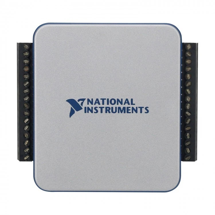
 Design with USB-6001 in Cirkit Designer
Introduction
The USB-6001, manufactured by NI (National Instruments), is a multifunction data acquisition (DAQ) device designed for seamless integration with computers via USB. This compact and versatile device offers analog input, digital I/O, and counter/timer functionalities, making it ideal for a wide range of measurement, monitoring, and control applications. Its plug-and-play USB connectivity ensures ease of use, while its robust design supports reliable performance in laboratory, industrial, and educational environments.
Explore Projects Built with USB-6001
 Open Project in Cirkit Designer
 Open Project in Cirkit Designer
 Open Project in Cirkit Designer
 Open Project in Cirkit Designer
Explore Projects Built with USB-6001
Open Project in Cirkit DesignerOpen Project in Cirkit DesignerOpen Project in Cirkit DesignerOpen Project in Cirkit DesignerCommon Applications
- Data logging and monitoring
- Sensor interfacing and signal acquisition
- Control systems and automation
- Prototyping and testing in research and development
- Educational experiments and demonstrations
Technical Specifications
Key Technical Details
| Parameter | Specification |
|---|---|
| Analog Input Channels | 8 single-ended or 4 differential |
| Analog Input Resolution | 14 bits |
| Analog Input Range | ±10 V, ±5 V, ±2 V, ±1 V |
| Maximum Sampling Rate | 20 kS/s (aggregate) |
| Digital I/O Channels | 12 (TTL logic levels) |
| Digital I/O Voltage Levels | 0–5 V |
| Counter/Timer Channels | 1 (32-bit resolution) |
| USB Interface | USB 2.0 (High-Speed) |
| Power Supply | USB-powered |
| Operating Temperature | 0 °C to 45 °C |
| Dimensions | 88.1 mm × 62.2 mm × 23.1 mm |
Pin Configuration and Descriptions
The USB-6001 features a 16-pin screw terminal block for easy connectivity. Below is the pinout configuration:
| Pin Number | Signal Name | Description |
|---|---|---|
| 1 | AI 0+ | Analog Input Channel 0 Positive |
| 2 | AI 0- | Analog Input Channel 0 Negative |
| 3 | AI 1+ | Analog Input Channel 1 Positive |
| 4 | AI 1- | Analog Input Channel 1 Negative |
| 5 | GND | Ground Reference |
| 6 | AO 0 | Analog Output Channel 0 |
| 7 | PFI 0 | Programmable Function Interface 0 |
| 8 | PFI 1 | Programmable Function Interface 1 |
| 9 | DIO 0 | Digital I/O Channel 0 |
| 10 | DIO 1 | Digital I/O Channel 1 |
| 11 | DIO 2 | Digital I/O Channel 2 |
| 12 | DIO 3 | Digital I/O Channel 3 |
| 13 | +5 V | +5 V Power Output |
| 14 | GND | Ground Reference |
| 15 | CTR 0 | Counter/Timer Channel 0 |
| 16 | AO GND | Analog Output Ground |
Usage Instructions
How to Use the USB-6001 in a Circuit
- Connect the Device to a Computer: Use a USB cable to connect the USB-6001 to a computer. Ensure the NI-DAQmx driver is installed on the computer for proper operation.
- Wiring the Inputs and Outputs:
- For analog inputs, connect the signal source to the appropriate AI+ and AI- pins.
- For digital I/O, connect the external device to the DIO pins, ensuring compatibility with TTL logic levels.
- For analog output, connect the load to the AO 0 and AO GND pins.
- Configure the Device in Software:
- Use NI software such as LabVIEW or Measurement & Automation Explorer (MAX) to configure the device.
- Set the desired sampling rate, input range, and other parameters.
- Acquire or Generate Signals:
- Use the software to acquire data from sensors or generate signals for control applications.
Important Considerations and Best Practices
- Power Supply: The USB-6001 is USB-powered, so ensure the USB port provides sufficient power.
- Signal Conditioning: For accurate measurements, use appropriate signal conditioning (e.g., filters or amplifiers) if needed.
- Grounding: Properly ground the device to avoid noise and ensure signal integrity.
- Software Compatibility: Ensure the NI-DAQmx driver and software are up to date for optimal performance.
Example Code for Arduino UNO Integration
Although the USB-6001 is primarily designed for use with NI software, it can interface with an Arduino UNO for digital I/O applications. Below is an example of how to read a digital signal from the USB-6001 using an Arduino UNO:
// Example: Reading a digital signal from USB-6001 using Arduino UNO
// Connect USB-6001 DIO 0 to Arduino pin 2

const int usb6001Pin = 2; // Arduino pin connected to USB-6001 DIO 0
int signalState = 0;      // Variable to store the signal state

void setup() {
  pinMode(usb6001Pin, INPUT); // Set Arduino pin as input
  Serial.begin(9600);         // Initialize serial communication
}

void loop() {
  signalState = digitalRead(usb6001Pin); // Read the digital signal
  Serial.print("Signal State: ");        // Print the signal state
  Serial.println(signalState);
  delay(500);                            // Wait for 500 ms
}
Troubleshooting and FAQs
Common Issues and Solutions
Device Not Recognized by Computer:
- Ensure the USB cable is securely connected.
- Verify that the NI-DAQmx driver is installed and up to date.
- Try connecting to a different USB port or computer.
Incorrect or No Signal Readings:
- Check the wiring and ensure proper connections to the input/output pins.
- Verify that the input signal is within the specified voltage range.
- Ensure the device is properly configured in the software.
Noise in Analog Signals:
- Use shielded cables and proper grounding to minimize noise.
- Add filtering or signal conditioning to the input signals.
Digital I/O Not Responding:
- Confirm that the external device is compatible with TTL logic levels.
- Check the software configuration for the digital I/O channels.
FAQs
Q: Can the USB-6001 be used with third-party software?
A: Yes, the USB-6001 can be used with third-party software that supports NI-DAQmx or provides APIs for data acquisition.
Q: What is the maximum cable length for USB connectivity?
A: The maximum recommended cable length for USB 2.0 is 5 meters. Use a powered USB hub if longer distances are required.
Q: Can the USB-6001 output analog signals?
A: Yes, the USB-6001 has one analog output channel (AO 0) for generating signals.
Q: Is the USB-6001 suitable for high-speed data acquisition?
A: The USB-6001 supports a maximum sampling rate of 20 kS/s, making it suitable for low- to medium-speed applications. For higher speeds, consider other NI DAQ devices.