How to Use MPS20N0040D PRESSURE SENSOR : Examples, Pinouts, and Specs
Introduction
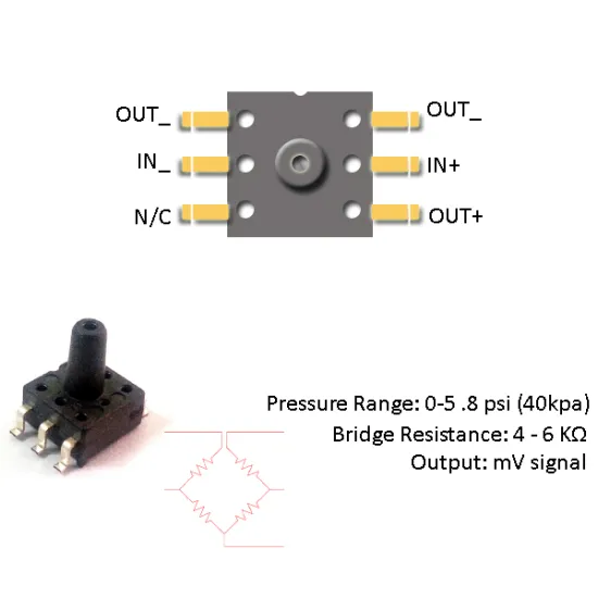
The MPS20N0040D is a piezoresistive pressure sensor that converts applied pressure into a linear and proportional electrical signal. This sensor is widely used in applications such as medical instrumentation, environmental controls, HVAC systems, and automotive pressure sensing.
Explore Projects Built with MPS20N0040D PRESSURE SENSOR
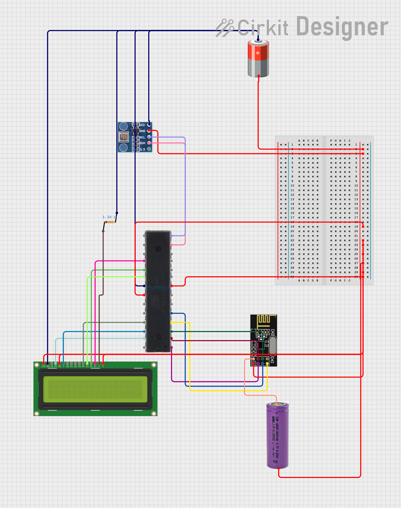
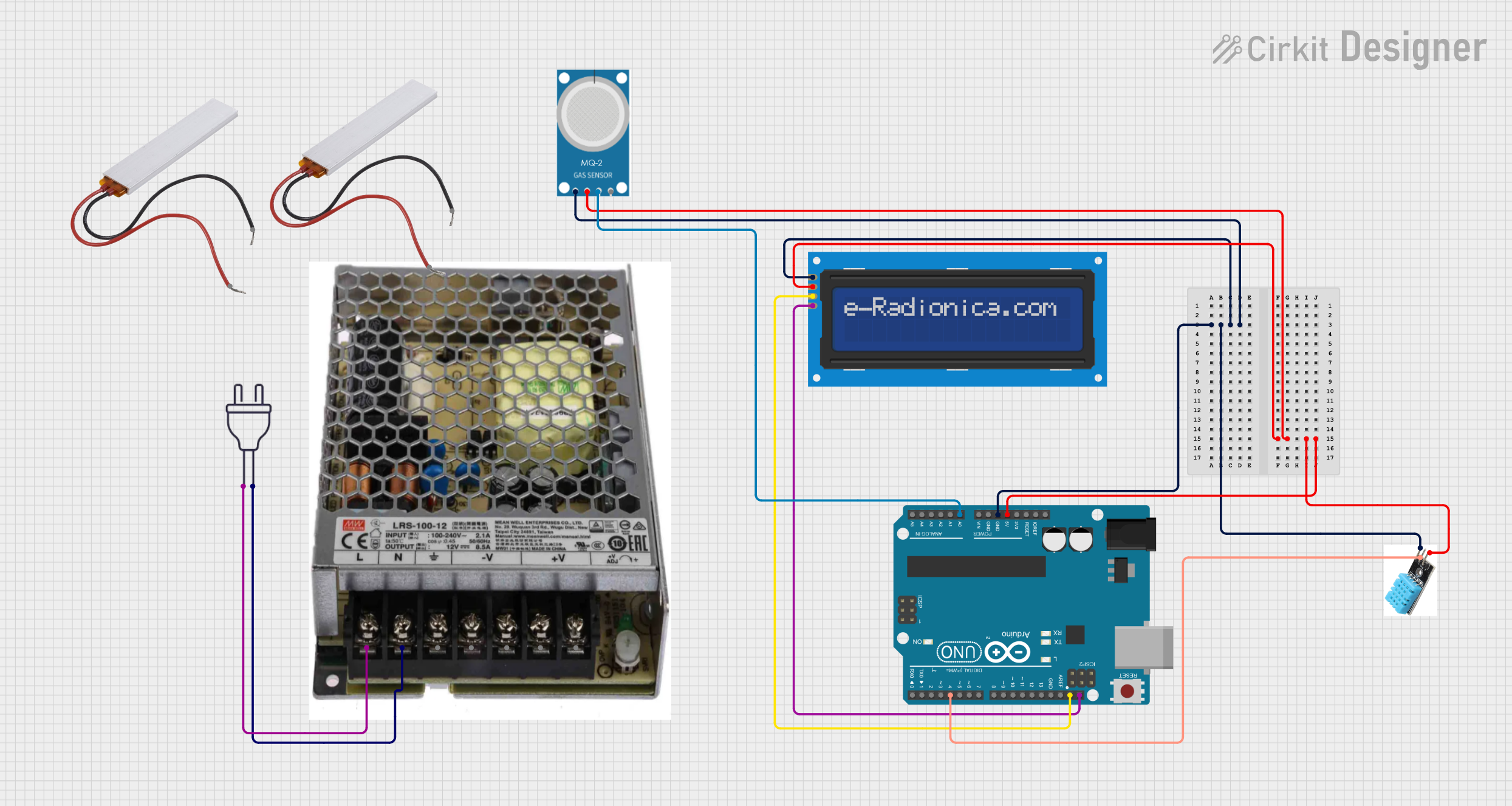
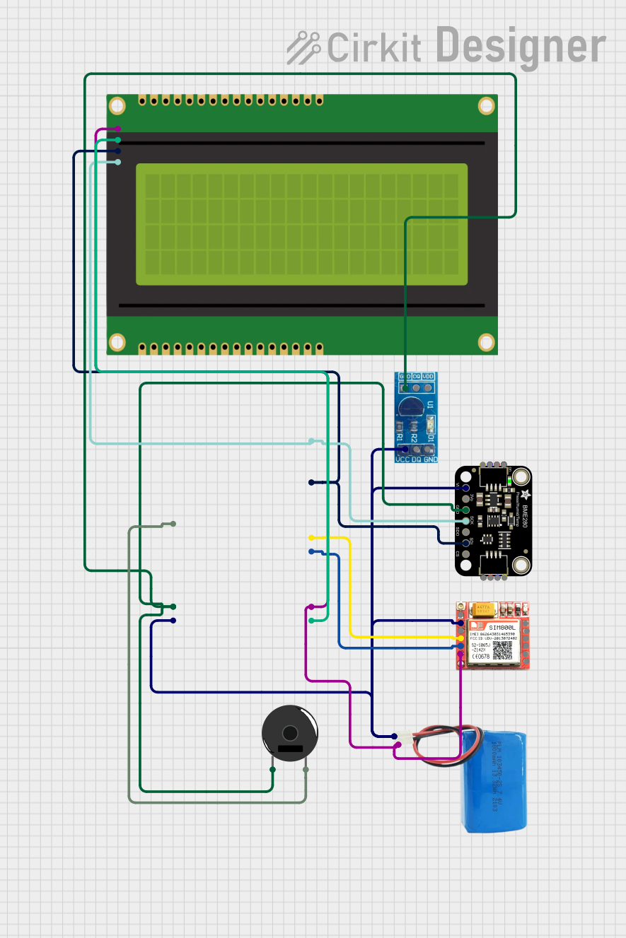

Explore Projects Built with MPS20N0040D PRESSURE SENSOR
Common Applications and Use Cases
- Blood pressure monitoring
- Air pressure measurement in HVAC systems
- Automotive tire pressure monitoring
- Industrial process control
- Weather station instrumentation
Technical Specifications
Key Technical Details
- Operating Voltage: 5V DC
- Output Voltage: 0.2V to 4.7V (proportional to pressure)
- Pressure Range: 0 to 40 kPa
- Sensitivity: Typically 5mV/kPa
- Linearity: ±1.5% F.S.
- Response Time: <2ms
- Operating Temperature: -40°C to +125°C
Pin Configuration and Descriptions
| Pin Number | Description |
|---|---|
| 1 | Vcc (Power Supply) |
| 2 | GND (Ground) |
| 3 | Vout (Signal Out) |
Usage Instructions
How to Use the Component in a Circuit
- Connect the Vcc pin to a 5V power supply.
- Connect the GND pin to the ground of the power supply.
- The Vout pin will output an analog voltage that is proportional to the pressure applied to the sensor. Connect this pin to an analog input on your microcontroller, such as an Arduino, to read the pressure.
Important Considerations and Best Practices
- Ensure that the power supply does not exceed 5V as it may damage the sensor.
- Avoid applying pressure that exceeds the sensor's maximum rating (40 kPa) to prevent permanent damage.
- Use a filtering capacitor between Vcc and GND to stabilize the power supply if necessary.
- For accurate readings, calibrate the sensor in the application environment.
Example Arduino Code
// Define the analog pin connected to the sensor's Vout
const int pressurePin = A0;

void setup() {
  // Initialize serial communication at 9600 baud rate
  Serial.begin(9600);
}

void loop() {
  // Read the analog value from the sensor
  int sensorValue = analogRead(pressurePin);
  // Convert the analog value to voltage (assuming a 5V supply)
  float voltage = sensorValue * (5.0 / 1023.0);
  // Convert the voltage to pressure in kPa
  float pressure = (voltage - 0.2) * (40.0 / 4.5);

  // Print the pressure value to the serial monitor
  Serial.print("Pressure: ");
  Serial.print(pressure);
  Serial.println(" kPa");

  // Wait for a short period before reading again
  delay(500);
}
Troubleshooting and FAQs
Common Issues Users Might Face
- Inaccurate Readings: Ensure the sensor is properly calibrated and that there are no leaks in the system where the sensor is installed.
- No Output Voltage: Check the power supply connections and ensure the sensor is receiving 5V.
- Sensor Not Responding: Verify that the sensor is within the operating temperature range and that it has not been exposed to pressures beyond its limit.
Solutions and Tips for Troubleshooting
- If the output voltage is stuck at a low or high value, ensure that the sensor is not damaged and that the pressure is within the measurable range.
- Use a multimeter to check the continuity of the sensor pins and the integrity of the connections.
- Implement software debouncing or hardware filtering if the output signal is noisy.
FAQs
Q: Can the MPS20N0040D sensor measure negative pressure? A: No, this sensor is designed to measure positive pressure only within its specified range.
Q: What is the lifespan of the MPS20N0040D sensor? A: The lifespan depends on the operating conditions, but it is generally designed for long-term stability and performance when used within its specified limits.
Q: How can I calibrate the sensor? A: Calibration involves applying known pressures to the sensor and recording the output voltage. These values are then used to create a calibration curve or equation to convert future readings to accurate pressure values.
Q: Is the MPS20N0040D waterproof? A: The sensor itself is not waterproof and should be protected from direct contact with liquids. Appropriate housing or sealing should be used for applications involving fluids.
This documentation provides a comprehensive guide to the MPS20N0040D pressure sensor, ensuring users can effectively integrate and utilize this component in their projects.